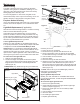
Service Manual 33” Wide Screen Fireplace with Full Feature Remote Control Model Number DF3033ST DCF44GS DFG3033 UL Part Number 6905060159 to 0959 IMPORTANT SAFETY INFORMATION: Always read this manual first before attempting to service this fireplace. For your safety, always comply with all warnings and safety instructions contained in this manual to prevent personal injury or property damage. Dimplex North America Limited 1367 Industrial Road Cambridge ON Canada N1R 7G8 1-888-346-7539 www.dimplex.
Table of Contents Operation. . . . . . . . . . . . . . . . . . . . . . . . . . . . . . . . . . . . . . . . . . . . . . . . . . . . . . . . . . . . . . . . . . . . . . . . 3 Maintenance . . . . . . . . . . . . . . . . . . . . . . . . . . . . . . . . . . . . . . . . . . . . . . . . . . . . . . . . . . . . . . . . . . . . . 5 Exploded Parts Diagram - Incandescent Lights . . . . . . . . . . . . . . . . . . . . . . . . . . . . . . . . . . . . . . . . . . 6 Replacement Parts List - Incandescent Lights . . . .
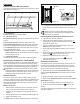
Operation Figure 2 Electric Fireplace Manual Control Batteries The manual controls for the fireplace are located in the upper right hand corner (Figure 1). Figure 1 C B Unlocked Locked A Child Lock Tab Child Lock control it is recommended to replace the batteries promptly, to maintain full functionality of the remote/fireplace. The remote control has a battery backup time of only several hours. Battery must be recycled or disposed of properly.
Figure 3 - Remote Control Functions A. B. C. D. E. F. G. H. I. J. K. L. M. N. Room Temperature Set Temperature Dimmer Flame Speed Control Sleep Timer Flame & Heat On/Off Temperature Down Temperature Up Dimmer Down Dimmer Up Flame Speed Down Flame Speed Up Sleep Timer Down Sleep Timer Up Disable Heat If desired, depending on the season, the heater on the unit can be disabled. The unit will operate in the same fashion, with remainder of the controls. To Disable - Press M and H at the same time.
Maintenance Figure 5 Glass Cleaning The glass is cleaned in the factory during the assembly operation. During shipment, installation, handling, etc., the glass may collect dust particles; these can be removed by dusting lightly with a clean dry cloth. To remove fingerprints or other marks, the glass can be cleaned with a damp cloth. To prevent scratching, do not use abrasive cleaners or spray liquids on the glass surface.
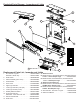
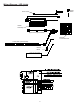
Exploded Parts Diagram - Incandescent Lights (6905060159 - 6905060359) 11 3 4 6 14 9 1 5 7 10 8 13 14 Replacement Parts List - Incandescent Lights 2 13. Remote Control DF3033ST Mod 0-D, DCF44GS Mod 0-B, DFG3033 Mod 0-A 433MHz - Silver Dimplex Logo . . . . . . . . 3000350100RP DF3033ST Mod E, DCF44GS Mod C, DFG3033 Mod B 2.4GHz - Red Dimplex Logo. . . . . . . . . . 3001070100RP 14. Remote Control Receiver DF3033ST Mod 0-D, DCF44GS Mod 0-B, DFG3033 Mod 0-A 433MHz Silver Dimplex Logo . . . .
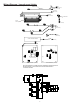
Wiring Diagram - Incandescent Lights (6905060159 - 6905060359) LINE (JP14 OR JP7) POWER CORD NEUTRAL (JP16 or JP9) 4 pin Molex (JP12 or JP4) NEUTRAL (JP15 OR JP10) On/Off Switch Heater Assembly LINE (JP13 OR JP8) LIGHTS (JP11 OR JP5) MOTOR (JP9 OR JP6) LOGSET AND LED HARNESS LOGS (JP7 OR JP3) JP4 JP10 JP5 JP9 JP2 JP6 JP8 JP7 JP3 RECEIVER BOARD 1 (433MHz) RECEIVER BOARD 2 (2.
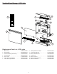
Exploded Parts Diagram - LED Lights (6905060659 - 6905060959) 13 3 12 10 6 4 8 9 5 7 11 1 14 2 Replacement Parts List - LED Lights 1. 2. 3. 4. 5. 6. 7. Media Tray . . . . . . . . . . . . . . . . . . . . . . . 0440410100RP Flicker Motor . . . . . . . . . . . . . . . . . . . . . 3000240200KIT Heater Assembly (with cutout) . . . . . . . . 2000330200RP On/Off Switch . . . . . . . . . . . . . . . . . . . . . 2800070200RP Power Cord . . . . . . . . . . . . . . . . . . . . . .
Wiring Diagram - LED Lights (6905060659 - 6905060959) Power Cord A LIVE A B B JP16 NEUTRAL JP12 PIN 4 L1 F D JP13 JP15 L1 N Heater Assembly PIN 1 PIN 2 PIN 3 Upper LED Light Assembly PIN 4 PIN 5 JP9 Lower LED Light Assembly JP7 Flicker Motor LOGSET AND LED HARNESS C LOGSET LED LIGHTS 9 JP11 PIN 6 Remote Control Receiver On/Off Switch
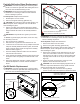
Partially Reflective Glass Replacement Figure 8 W ARNING: If unit was operating prior to servicing allow at least 10 minutes for light bulbs and heating element to cool off to avoid accidental burning of skin. W ARNING: Disconnect power before attempting any maintenance or cleaning to reduce the risk of electric shock or damage to persons. Top Cover Tools Required: Phillips head Screwdriver 1. Slide fireplace out from mantel. 2. Remove front glass assembly (glass lifts off).
Figure 10 6. Flip the Baffle and Switch Mount Bracket over and rest it across the front half of the fireplace. 7. Locate the Remote Switchboard mounted on the underside of the Baffle panel on the right side (Figure 10) and disconnect the white wire harness that leads to the remote control receiver. 8. The Remote Switchboard is fastened to the underside of the Baffle and Switch Mount Bracket by two (4) mounting studs, one on each side (Figure 10).
into the rubber bushing on the Flicker Motor shaft (Figure 11). ! NOTE: When removing the Flicker Rod, damage may occur if bent excessively. If the Flicker Rod is damaged, replace to insure proper operation. 7. Cautiously bend the Flicker Rod enough so that the remaining end of the Flicker Rod clears the plastic bushing on the left (Figure 11). 8. Remove Flicker Rod (replace and reassemble if Flicker Motor does not need to be changed at this point). 9.
to remove. On newer receivers the antenna is built into the board. 7. The Remote Control Receiver is fastened to the underside of the top panel by 7 Mounting Studs, one in each corner, and 3 off center as shown in Figure 12. Either squeeze each mounting stud’s clasp to release, or use side cutters to cut and remove each of the Mounting Studs on the board. ! NOTE: If mounting studs are cut, replacement mounting studs will need to be inserted through the top panel. Replacement Mounting Studs are supplied. 8.
5. 6. 7. 8. 9. 10. 11. 12. wire ends that run to the top of the firebox. 9. Connect the stripped wires with the wires from the new light sockets, using an appropriate wire connector (customer supplied). 10. Wrap all of the wires together with the protective covering and secure with tie wraps. 11. Reassemble firebox in reverse order as above and replace in mantel. enough slack of power cord from within the firebox to work with.
Troubleshooting Guide PROBLEM CAUSE SOLUTION General Circuit breaker trips or fuse blows when unit is turned on Short in unit wiring. Trace wiring in unit. Improper circuit current rating Additional appliances may exceed the current rating of the circuit breaker or fuse. Plug unit into another outlet or install unit on a dedicated 15 amp circuit. Unit turns on or off by itself Remote Control has a similar frequency to other remotes in the area.
PROBLEM CAUSE SOLUTION Heater Heater is not turning off (Manually) Heater is not turning on (Manually) Heater is turning off after a couple of minutes of operation Heater emits an odor Heater fan turns on but heater lacks heat Heating element is glowing red Improper operation Refer to Operation Section Defective Remote Switchboard Replace Remote Switchboard Defective Remote Control Receiver Replace Remote Control Receiver. Initialize Remote Control and Remote Control Receiver.