
Firebox Service Manual

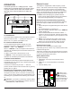
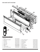
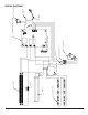


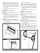


Table Of Contents
- OPERATION
- EXPLODED PARTS DIAGRAM
- WIRING DIAGRAM
- PREPARATION FOR SERVICE
- INSTRUCTIONS FOR REMOVING FROM WALL
- LED LIGHT STRIPS REPLACEMENT
- LED DRIVER BOARD REPLACEMENT
- FLICKER MOTOR/FLICKER ROD REPLACEMENT
- ELEMENT REPLACEMENT
- HIGH TEMPERATURE CUTOUT REPLACEMENT
- BLOWER/FAN REPLACEMENT
- ON/OFF SWITCH REPLACEMENT
- REMOTE SWITCHBOARD REPLACEMENT
- REMOTE CONTROL RECEIVER REPLACEMENT
- POWER CORD REPLACEMENT
- ASSEMBLY PART PICTURES
- TROUBLESHOOTING GUIDE

4 www.dimplex.com
EXPLODED PARTS DIAGRAM
Replacement Parts List
12
6
1
2
3
4
14
10
11
7
13
8
16
9
Element1. .........................2200510500RP
Partially Reective Glass2. . . . . . . . . . . . 5901920100RP
Blower/Fan3. . . . . . . . . . . . . . . . . . . . . . . 5300260100RP
Front Glass4. ......................5901930100RP
Power Cord5. ......................8400320100RP
Flicker Motor6. .....................2000220100RP
Flicker Rod 7. ......................5901910100RP
Cutout8. ..........................2300200100RP
LED Light Strips9. . . . . . . . . . . . . . . . . . . 3000830102RP
Remote Control Receiver10. . . . . . . . . . . . 3000820100RP
Remote Switchboard11. ...............3000820300RP
LED Driver Board12. . . . . . . . . . . . . . . . . . 3000810100RP
On/Off Switch13. . . . . . . . . . . . . . . . . . . . . 2800210200RP
Terminal Block14. ....................4000070100RP
Capacitor15. ........................3200030100RP
Remote Control16. ...................3000370600RP
Glass Ember Bed17. . . . . . . . . . . . . . . . . . 1400070100RP
Hardware Kit18. .....................9600350100RP
Plastic Media Tray19. .................5901940100RP
19