Contact Details Please note that some of the contact details on this PDF document may not be current. Please use the following details if you need to contact us: Telephone: 0844 879 3588 Email: customer.services@gdcgroup.co.uk The customer support section of our website also features a wide range of information which may be of use to you and is available 24 hours a day.
Installation User Manualand Operating Instructions MODUCONTROL Controller forHeat the he e LLAB AB Air-to-Water range of pumps umps Pump forheat Outdoor Installation FD 8910 English LAB 07M 7M 9M LAB 09M LAB 11M
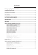
Contents Warnings regarding the documentation .......................................................................... 5 Fundamental safety rules .................................................................................................. 5 Description of the controller ............................................................................................. 6 User interface .....................................................................................................................
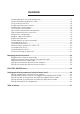
Contents Enabling domestic hot water preparation.................................................................. 17 Power for producing domestic water......................................................................... 18 Valve switch pause time ............................................................................................ 18 Enable room thermostat control................................................................................. 18 Enabling flow switch bypass ....................
1 Warnings regarding the documentation 1.1 Use in compliance with the documentation The Dimplex LAB units are constructed according to the European technical standards and safety regulations. The heat pump is designed and built for heating and domestic hot water production (DHW). In the event of improper use, dangers to the user or third parties may arise, as well as damage to the heat pump and other objects. Any use not expressly indicated in this manual is not permitted.
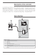
Description of the controller The control panel of the unit allows the rapid setting and display of the working parameters of the heat pump. The display consists of 4 figures and various LEDs for indicating the operational mode, the display of the current parameters and of any alarms that have been triggered. The controller is sup- With the PR30 it is also possible to view a summary of any alarms that have been triggered.
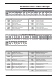
MODUCONTROL default settings USER menu - (Password 000) StA StF bnF StC bnC CSt SF1 tF1 SF2 tF2 SC1 tC1 SC2 tC2 SAS bAS 0 1 2 3 4 5 6 7 8 9 A B C D E F 1 12 3 30 3 2 12 18 7 30 30 0 20 18 47 3 LAB Index - String Meaning of parameter 0 - StA Selection of operating mode 8 - SF2 Cooling curve setting 3 1 - StF Cooling set temperature 9 - tF2 Cooling curve setting 4 2 - bnF Cooling hysterisis A - SC1 Heating curve setting 1 Index - String Meaning o
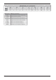
ELECTRIC HEATER menu - (Password 001) LAB Index - String SrA brA Sri bri tA1 tA2 bA 0 1 2 3 4 5 6 4 1 3 1 2 -30 2 Meaning of parameter 0 - Sra Freeze protection activation temperature 1 - brA Freeze protection hysterisis 2 - Sri Supplementary electric heater setpoint 3 - bri Supplementary electric heater hysterisis 4 - tA1 External air temperature setpoint 1 5 - tA2 External air temperature setpoint 2 6 - bA Hysterisis on air temperature setpoints EN - 8
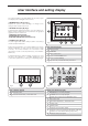
User interface and setting display The main user interface has a LED display with a touch-keys pad. The display is are arranged in three menus: A • READINGS menu (key (C) Fig.1) Displays the system’s current readings, no changes to the settings can be made in this menu. • SETTINGS menu (key (D) Fig.
READINGS menu To access the readings menu, press the key in (Fig.4); once the readings menu has been accessed, the monitor will display the readingis index and a 3-character string that identifies it; the string will be displayed for one second, after which it is replaced by the value of the reading itself. To move on to the next reading, press the key in (Fig.5); to go back to the previous one, press the key in (Fig.6).
USER menu To access the USER menu, press the key in (Fig.7). Once the key has been pressed, you must insert the password to access the various menus; to access the user menu, the password is 000 (displayed by default). To enter a different passwords, use the arrow keys. When you have inserted the correct password, press the key in (Fig.7).
Setting of proportional cooling hysterisis Index - String MIN value 1°C MAX value Parameter function 20°C This parameter indicates the proportional band applied to the cooling set temperature; this band produces the optimised management of the compressor, only switching it on if the inlet/outlet water temperature (depending on the type of control set by parameter (0) in the installer menu) is greater than the cooling work set (parameter (1) user menu) plus the value of this parameter.
Setting Cooling curve setting 1 Index - String MIN value MAX value Parameter function -20°C 26°C This parameter indicates the maximum value of the cooling set temperature, corresponding with the minimum outside air temperature (index (7) user menu). This parameter is only visible if the compensation function has been activated (index (5) user menu).
heating curve set 3 Index - String MIN value MAX value Parameter function 25°C 65°C This parameter indicates the minimum value of the heating set temperature, corresponding with the maximum outside air temperature (index (C) user menu). This parameter is only visible if the compensation function has been activated (index (5) user menu).
INSTALLER menu To access the INSTALLER menu, press the key in (Fig.9). Once the key has been pressed, you must insert the password to access the various menus; to access the user menu, the password is 030. To enter a different passwords, use the arrow keys. When you have inserted the correct password, press the key in (Fig.9).
Setting Heating limit flow temperature Index - String MIN value MAX value Parameter function 30°C 70°C The heat pumps monitor this set temperature (input or output), beyond which the compressor is switched off immediately and automatically; this threshold is called FORCE-OFF. MIN value MAX value Parameter function 0.5°C 20°C In heating, this is the temperature threshold below the force-off, which reactivates the start-up of the compressor after the switching off for force-off.
Setting supplementary electric heater Index - String MIN value 0 MAX value Parameter function 3 This parameter indicates the presence of a supplementary electric heater.
Power for producing domestic water Index - String MIN value 0% MAX value Parameter function 100% In those units that can produce domestic water, once this function has been activated it is possible to decide the percentage of power to use for the production. This function allows you to set a threshold to guarantee reduced energy consumption during domestic water production.
Max external temperature for operation Index - String MIN value MAX value Parameter function 0 70 This parameter lets you establish the room temperature threshold above which the heat pump is disabled; once the threshold has been exceeded, the compressor and pump are switched off.
Selection logic for dynamic FORCE OFF The adjacent diagram shows the logic for the dynamic FORCE OFF function; this logic enables optimal management of electric in accordance with the unit's operating heater limits. Example: The aim is to produce at domestic hot water with a setpoint of 55° an air temperature of -10°. Based on the parameters entered in the example, FORCEOFF will intervene at 45°. The compressor will continue to work until an output temperature of 45° is reached.
Air temperature limit 2 Index - String MIN value MAX value Parameter function -25°C 45°C This parameter indicates the outside air temperature corresponding to the maximum water temperature limit (St2 parameter, r indicator) that can be produced by the compressor. MIN value MAX value Parameter function 0°C 70°C This parameter indicates the maximum water temperature limit produced by the compressor with outside air temperature equal to parameter LA2 (indicator q).
Managing the electric heater The units with moducontrol offer the possibility to manage an electric heater; this heater can be managed in different ways: • supplementary (the simultaneous use of the heat pump and the electric heater); • anti-freeze, or replacement (the heat pump compressor is switched off and the electric heater alone is activated); The operational specifications of both modes are shown in the diagrams below.
ELECTRIC HEATER menu To access the ELECTRIC HEATER menu, press the key in (Fig.14). Once the key has been pressed, you must insert the password to access the various menus; to access the user menu, the password is 001. To modify the value of the passwords, use the arrow keys. When you have inserted the correct password, press the key in (Fig.14).
Setting supplementary electric heater setpoint Index - String MIN value MAX value Parameter function 0°C 65°C This parameter indicates the deviation from the heating setpoint, for switching off the electric heater (if active) in supplementary mode; as shown in Fig.12 on the previous page (Parameter Sri).
Table of DIP-SWITCH configuration Dip-switch (B) Apart from the parameters that can be inserted from the electronic control panel, the units are fitted with a series of dip-switches for managing some options and functions of the machine. Remember that some of the options that can be managed from the panel are bound to a specific setting of some dipswitches.
Table of alarms The units have two types of malfunctioning warning: • pre-alarm • alarm The first type is indicated by the flashing of the red indicator light on the display; by pressing the bell key, you can display the alarm list (with index and cause shown in the table below). A pre-alarm remains such for 60 seconds; if the condition that caused it does not disappear within this time, it becomes an alarm.
10 110 High force gas temperature 11 111 No compressor delivery pressure transducer 12 112 High pressure 13 113 No defrosting probe 14 114 15 115 No compressor suction pressure transducer Low pressure 16 - 17 117 Pump thermomagnetic switch 18 118 High pressure capacity control 19 119 Low pressure capacity control 20 120 Discharge temperature capacity control 21 121 22 23 24 122 123 124 25 26 125 126 27 28 29 30 127 128 129 130 31 131 Bemf error (chiller inverter) err
32 132 33 34 35 36 37 40 133 134 135 136 137 140 41 42 43 44 45 141 142 143 144 145 46 47 146 147 51 54 55 151 154 155 -- 156 Excessive temperature of cooling blade Overcurrent in acceleration Overcurrent at constant speed Overcurrent in deceleration Undervoltage on BUS DC Overvoltage on BUS DC PFC Converter Fault Error in the PFC module Overcurrent in acceleration Overload Overcurrent at constant speed Overcurrent in deceleration Compressor not connected correctly No communication Error in cool
Declaration of Conformity www.dimplex.
Glen Dimplex Deutschland GmbH Geschäftsbereich Dimplex Am Goldenen Feld 18 D-95326 Kulmbach Subject to alterations and errors. +49 (0) 9221 709 565 www.dimplex.