Luft/WasserWärmepumpe für Schwimmbaderwärmung zur Außenaufstellung Installation and Operating Instructions English Instructions d’installation et d’utilisation Français Montage- und Gebrauchsanweisung Air-to-Water Heat Pumps for Swimming Pool Heating (Outdoor Installation) Bestell-Nr. / Order no. / No de commande : 452159.66.
Table of contents 1 Please Read Immediately .............................................................................................................E-2 1.1 Important Information:............................................................................................................................. E-2 1.2 Legal Regulations and Directives ........................................................................................................... E-2 1.3 Energy-Efficient Use of the Heat Pump .......
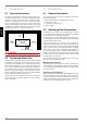
1 1 Please Read Immediately 1.1 Important Information: ATTENTION! When transporting the heat pump, ensure that it is not tilted more than 45° (in any direction). ATTENTION! English The heat pump and transport pallet are only joined by the packing film. 1.3 Energy-Efficient Use of the Heat Pump To maintain heat pump efficiency, it is particularly important to keep the temperature difference between the domestic hot water and heat source to a minimum.
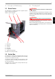
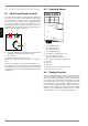
3 Scope of Delivery 3.1 4 ATTENTION! Basic Device The heat pump is of compact design and is supplied complete with the components listed below. When transporting the heat pump, ensure that it is not tilted more than 45° (in any direction). Use the wooden pallet for transporting the heat pump to its final installation location. Either a lifting truck or 3/4" pipes fed through the holes in the base plate or frame can be used for transporting the heat pump. R407C is used as refrigerant.
5 Installation 5.1 General Information The device should always be installed on a permanently smooth, even and horizontal surface. To counteract development of any solid-borne sound, the entire frame (and its supporting surface) should be in contact with the floor. If this is not possible, additional constructional measures to improve sound insulation may need to be provided by the customer. It must be possible to carry out maintenance work without hindrance.
7.2 Electrical Connection 7 Start-Up Depending on device type, the heat pump is connected to the power supply via a standard 3-core cable (1-phase devices) or standard 5-core cable (3-phase devices). 7.1 The cable(s) is(are) to be provided by the customer. The conductor cross section is selected in accordance with the power consumption of the heat pump (see Appendix Device Information) and the applicable VDE (EN) and VNB regulations.
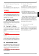
8 8 Description of Functions 8.1 8.2 Controller Board Heat Pump Remote Control The heat pump can be switched on and off inside the building via the remote control. In this context, switching off means the device is switched to a “standby” function, i.e. the frost protection function remains active as long as voltage is supplied to the heat pump. The filter pump runs when the air temperature is <5 °C. The heat pump runs when the water temperature is <10 °C.
11 Maintenance / Cleaning 9.1 Maintenance To protect the paintwork, avoid leaning or putting objects on the device. External heat pump parts can be wiped with a damp cloth and domestic cleaner. ATTENTION! Never use cleaning agents containing sand, soda, acid or chloride as these can damage the surfaces. To prevent faults due to sediments in the titanium heat exchanger of the heat pump, ensure that the heat exchanger cannot be contaminated (water treatment and filter system necessary).
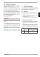
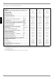
12 12 Device Information 1 Type and order code 2 Design 2.1 Degree of protection according to EN 60 529 for compact devices and heating components 2.2 Installation location 3 Performance data 3.1 Operating temperature limits: LAS 10MT LAS 15MT LAS 22TT IP 24 IP 24 IP 24 Outdoors Outdoors Outdoors English Heating water flow / return flow 1 °C / °C Up to 40 / above 10 Up to 40 / above 10 Up to 40 / above 10 Air °C -10 to +35 -10 to +35 -10 to +35 kW / kW 22.3 / 4.4 2 3.
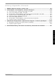
Anhang / Appendix / Annexes 1 Maßbild / Dimension drawing / Schéma coté ............................................................................ A-II 2 Stromlaufpläne / Circuit diagrams / Schémas électriques ...................................................... A-III 2.1 2.2 2.3 2.4 2.5 2.6 2.7 2.8 3 Steuerung / Control / Commande LAS 10MT - LAS 15MT.................................................................... A-III Last / Load / Charge LAS 10MT - LAS 15MT ..................................
A-II %RvWH GH MRQFWLRQ pOHFWULTXH F{WH UpYLVLRQ (OHFWU FRQQHFWLRQ ER[ LQVSHFWLRQ VLGH HOHNWULVFKHU $QVFKOXVVNDVWHQ 5HYLVLRQVVHLWH (FRXOHPHQW GH O¶HDX GH FRQGHQVDWLRQ &RQGHQVDWH GUDLQ .RQGHQVDWDEODXI XPODXIHQG FLUFXPIHUHQWLDO FLUFRQIpUHQWLHO &{WH GH VRXIIODJH G¶DLU $LU GLVFKDUJH HQG /XIWDXVEODVVHLWH 6HQV GX ILX[ G¶DLU 'LUHFWLRQ RI DLU IORZ /XIWULFKWXQJ *UXQGUDKPHQ %DVH IUDPH &KkVVLV Anhang · Appendix · Annexes .
2.2 2.1 Steuerung / Control / Commande LAS 10MT - LAS 15MT 2.2 Last / Load / Charge LAS 10MT - LAS 15MT www.dimplex.
2.3 2.
2.
2.6 2.6 Last / Load / Charge LAS 22TT 1HW] Â 0DLQV Â 5pVHDX < 8 PLQ /LHIHU]XVWDQG U S P 'HOLYHU\ FRQGLWLRQV W PLQ GpSDUW XVLQH Anschlussplan / Terminal diagram / Schéma de branchement LAS 22TT 6FKDOWUDXP 6ZLWFK ER[ %RvWH GH GLVWULEXWLRQ $QVFKOXVVOHLWXQJ Â &RQQHFWLQJ OHDG Â /LJQH GH UDFFRUGHPHQW JH JQ Â \H JQ Â MD YH 1HW] Â 0DLQV Â 5pVHDX Anhang · Appendix · Annexes 2.
2.
3 3 Hydraulische Prinzipschemen / Hydraulic block diagrams / Schémas hydrauliques 3.
3.2 3.
4 4 Konformitätserklärung / Declaration of Conformity / Déclaration de conformité Anhang · Appendix · Annexes A-X
Glen Dimplex Deutschland GmbH Geschäftsbereich Dimplex Am Goldenen Feld 18 D-95326 Kulmbach Irrtümer und Änderungen vorbehalten. Subject to alterations and errors. Sous réserve d’erreurs et modifications. +49 (0) 9221 709 565 www.dimplex.