
Operating instructions


Access to the controls
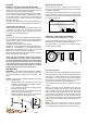
The controls cover (see ‘x’ in Fig. 1) on your heater has a
latch which may be locked shut if desired using a small bladed
screwdriver - see Fig. 3.
To open the cover insert the blade of the screwdriver in the
small slot and rotate a quarter of a turn clockwise to disengage
the latch. The cover may then be hinged back towards the wall
for access to the controls.
Operation - Thermostat only models
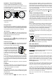
Control of Output and Temperature (see Fig. 4)
The switch marked O and I controls the electricity supply to the
heating elements. The OFF position is marked O.
The switch marked I - II (half heat – full heat) provides a
choice of output as desired.
Thermostat Operation
The heater is tted with an adjustable thermostat enabling
the room temperature to be controlled by adjusting the setting
accordingly. The
* setting represents a room temperature of
approximately 5°C and may be used for protection against
frost. Higher temperature settings range from 1-6 (max.)
creating a room temperature of approximately 30°C.
A neon indicator light glows when the appliance is actually
heating.
Switch on the heater and turn the thermostat knob to mark
6 opposite the indicator mark (located on centre right of the
knob - see Fig. 4 & 5), and set selector switch to full heat
output to warm the room rapidly. When the room temperature
has reached the desired level, turn the thermostat knob back
slowly until the thermostat just clicks off. The heater will then
maintain the room temperature at the chosen level, provided
that the correct size of heater has been selected for the room
to be heated.
NOTE – Should your heater fail to come on when the
thermostat knob is at a low setting, this may be due to the
room temperature being higher than the thermostat setting.
General
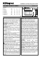
NOTE: The PLX Convector is designed for wall mounting on
the wall brackets supplied. The wall brackets supplied with the
appliance must be used. It should only be operated when in
the upright position as shown.
All models are splashproof to IP24 standard.
Models PLX…TI are tted with a 24 hour programmable timer.
Models PLX…TX are tted with a 7 day programmable timer.
Models PLX…NC are tted with no controls, for use with
external thermostatic or programming controllers.
Before connecting the heater check that the supply voltage is
the same as that stated on the heater.
Please note that lit cigarettes, candles and oil burners,
combined with the convection effect of electric heaters
can cause soot deposits to build up on the surface directly
above and to the sides of the heater. This is not the fault
of the heater. Extensive burning of candles or smoking
in the operating environment of this product can produce
heavy discoloration within a few months of use.
Wall Mounting
IMPORTANT – The wall brackets supplied with the appliance
must be used. The heater should be positioned observing
the minimum clearances stated around the heater - see
Fig. 1.
DO NOT locate the heater immediately below a xed socket
outlet or connection box.
1. Remove wall mounting bracket from the back of
the heater by depressing the spring latch at the top
of each bracket - see Fig. 2.
2 . F i x t h e w a l l b r a c k e t s e c u r e l y t o t h e w a l l t h r o u g h t h e
four screw holes provided.
3. Present the heater to the wall bracket, and engage
lower slots in the back with bracket.
4. Raise the heater to upright position and push the
heater onto brackets to engage top latch.
Fig. 3
Fig. 4
Fig. 2
255
MIN
Electrical
WARNING – THIS APPLIANCE MUST BE EARTHED
The electrical installation must be carried out by a competent
electrician, and be in strict accordance with the current I.E.E.
regulations for Electrical Equipment in Buildings.
The heater is tted with a length of exible cable type H05VV-F
size 3 x 1.0mm
2
on models PLX 500 - 2000 and size 3 x 1.5mm
2
on PLX 3000 models, for connection to the xed wiring of
the premises through a suitable connection box positioned
adjacent to the heater.
The supply circuit to the heater must incorporate a double pole
isolating switch having a contact separation of at least 3mm.
Supplementary Earth Bonding
Should Equipotential Earth Bonding be required the earthing
conductor in the supply cord is deemed to provide the
supplementary bonding connection (see Regulation 544.2.5,
17
th
Edition I.E.E. Wiring Regulations).