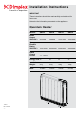
Installation Instructions A world of expertise IMPORTANT These instructions should be read carefully and retained for future use. Note also the information presented on the appliance. Quantum Heater 11115-5 Rev. 123/125 -1- Models: QM070 QM100 QM125 QM150 Boost Output 230/240V~: 567/630W 792/880W 1017/1130W 1242/1380W Storage Element Rating 230/240V~: 1435/1560W 2042/2220W 2540/2760W 3024/3300W Rated Charge Period: 7.
IMPORTANT WARNING - THE SURFACE OF THIS HEATER CAN BE HOT. WARNING - THIS APPLIANCE MUST BE EARTHED. IMPORTANT These instructions should be read carefully and retained for future use. Note also the information presented on the appliance. • The installation must be carried out by a suitably qualified individual in accordance with the latest IEE Regulations for electrical equipment.
Where particularly vulnerable people are likely to be left unsupervised in the vicinity of the heater we recommend that a guard is fitted around the heater, as is normal with heating appliances in similar circumstances. A range of guards specially designed for Dimplex heaters is available. If you require further information on these guards, please see contact details on back page of the Operating Instructions. CAUTION: DO NOT COVER SURFACES OF THE HEATER AND DO NOT OBSTRUCT THE AIR OUTLET GRILLE.
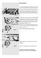
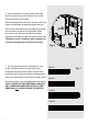
Preparation 1. Place the heater flat on the ground with arrows printed on the base of the carton pointing upwards. Open the carton at the bottom, slide the heater out of the carton by at least 200mm exposing the feet and the fixing kit located within the packaging on Fig. 1 the right hand side. Remove the feet and the fixing kit. 2. Secure the feet to the heater. For models QM070 and QM100 two locations are possible indicated by X and Y markings visible on the base of the heater.
3. Ensure the heater is stable before removing the screws which hold the grille panel in position. Set the grille to one side. Fig. 3 4. Remove the two screws located towards to bottom of either end of the heater, which retain the heater sides. Push the left hand and right hand sides vertically upwards to release each side from its securing points. Fig. 4 5.
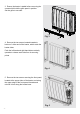
Installing the Heater The heater must be securely fixed to a wall. Screws with suitable wall fixings for solid walls are provided. If other wall types are encountered it is the installer who must choose the most suitable fixing. SUGGESTED FIXINGS SOLID BRICK/BLOCK: No. 10 size high temperature resistant plastic inserts, 8mm drill bit. Drill hole 15mm deeper than plastic insert length. PLASTERBOARD - If possible locate studding and use No.
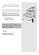
6. Place the heater in its final position and mark the fixing holes through the location holes visible through the back of the heater. Mark the fixing positions at the two extreme ends of the heater with the heater pushed tight against the wall. Remove the wall bracket from the heater by removing the two screws at each end of the bracket. Place the heater to one side and reposition the bracket against the wall aligning it with the location marks.
Warning: Before obtaining access Electrical Connections to terminals, all supply circuits 8. The heater leaves the factory configured to operate with two mains supplies, a 24 hour must be disconnected. Two Mains Supplies supply and an off peak switched supply. Storage / Fan circuit Ensure the brown wire is connected to the terminal marked L. L N OFF PEAK Fig. 8 L N PEAK 24 HOURS EARTH (BOTH SUPPLIES) Ensure the blue wire is connected to the terminal marked N.
. The mains cable entry bushes and terminal blocks will be visible on the right hand side of the unit. Insert the mains cables through the cable gland at the bottom of the heater in readiness for connection. IMPORTANT - Only heat resistant ordinary polyvinyl chloride sheathed flexible cord should be used, the following codes apply; IEC - 60227 IEC57 or CENELEC - H05V2V2-F Fig.
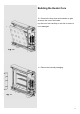
Building the Heater Core 10. Remove the inner front and insulation to gain access to the core of the heater. Lay the inner front carefully to one side to ensure it is not damaged. Fig. 10 11. Remove the internal packaging. Fig.
Bricks The bricks are supplied separately to the heater in packs of three. The reference number is 047243. 12. The bricks have several grooves on one surface for locating around the elements. The two slots through the centre of the brick create the air passages within the core. Position the first brick of the bottom row to the right, firmly pressed against the side insulation with the Fig. 12 element grooves facing upwards and fitting neatly around the element. Angle the element upward to fit the brick.
14. The third row of brick is positioned in a manner similar to the first row. Again be careful not to damage or dislodge the element. Fig. 14 15. Fit the fourth row of brick above the third row in the upside position. Repeat for the fifth and sixth rows of brick built around the third element to complete the core build. Fig. 15 16. Remember the top row of brick must be fitted upside down. Check that all the bricks are secure and evenly located. Fig.
17. Close the core by refitting the inner front panel complete with insulation. Ensure the bottom edge is located inside the chassis and that the screws are tightly secured down each edge. Fig. 17 IMPORTANT Double check all mains connections are secure and excess cable is restrained and not in contact with any of the heater casing. ON NO ACCOUNT SHOULD ANY SURPLUS CABLE BE PUSHED INSIDE OR BEHIND THE HEATER. Once installed DO NOT attempt to reposition the heater without first unloading the bricks.
IMPORTANT During the initial operation some odour may be noticed due to the newness of materials used in manufacture. This is normal and will disappear after a short period of use. It is however advisable to keep the room well ventilated. Clean the outlet grille and adjacent surfaces after the first operation as some dust may be produced when the heater is first used. 21°C 1 1 ‘Child Lock’ will apprear on the screen, repeat to reverse. See the Operating Instructions for further details.
- 15 -
MANUAL RE-SET RF MODULE Boost Neutral Red Fan No. 1 No. 2 White Core Peak L N L N Off Peak Earth User Interface Neutral Earth Live Bi-metal Neutral Element Neutral No.