Owner’s Manual Revillusion® Built-in Electric Firebox Models: RBF30 (6909780100), RBF30WC (6909780200), RBF36 (6909790100), RBF36WC (6909790300), RBF36P (6909790200), RBF36PWC (6909790400), RBF42 (6909800100), RBF42WC (6909800200) IMPORTANT SAFETY INFORMATION: Read this manual first before attempting to install or use the Revillusion® Built-in Electric Firebox. Always comply with the warnings and safety instructions contained in this manual to prevent personal injury or property damage.
Table of Contents Welcome.............................................................3 IMPORTANT INSTRUCTIONS........................... 4 Specifications......................................................6 Installation...........................................................7 Electrical..............................................................9 Operation..........................................................17 Maintenance.....................................................20 Warranty.........
Welcome Thank you for purchasing a Revillusion® Built-in Electric Firebox by Dimplex. Please use our convenient online registration page to record your model and serial numbers for future reference at: www.dimplex.com/register Model Number MODEL / CAT NO MOD SERIAL NO Serial Number CAUTION: Read all instructions and warnings carefully before starting installation. Failure to follow these instructions may result in a possible electric shock or fire hazard and will void the warranty.
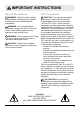
IMPORTANT INSTRUCTIONS Basic Precautions When using any electrical appliance, basic precautions should always be followed to reduce the risk of fire, electric shock, and injury to persons. These precautions include: ① Read all instructions before using the Revillusion® Built-in Electric Firebox. DANGER: High temperatures may be generated under certain abnormal conditions. Do not partially or fully cover or obstruct the front of the firebox. ② This firebox is hot when in use.
IMPORTANT INSTRUCTIONS Special Precautions FCC Compliance WARNING: Remote control contains a small battery. Keep away from children. If swallowed, seek medical attention immediately. CAUTION: This unit has been tested and found to comply with the limits for Class B digital device, pursuant to part 15 of the FCC Rules. These limits are designed to provide reasonable protection against harmful interference in a residential installation.
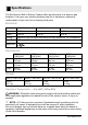
Specifications The Revillusion® Built-in Electric Firebox offers an alternative to a wood or gas fireplace. It can give your existing fireplace new life or transform a cabinet or media center of your own into a stunning focal point. Electrical Volts 120 V 60 Hz 208 V 60 Hz 240 V 60 Hz Amps 10.83 A 9.5 A 10.
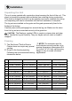
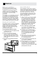
Installation Unpacking the Unit The unit comes packed with a protective sheet covering the front of the unit. This sheet is intended to prevent dust and debris from entering during construction. This sheet is designed so that it can be partially removed to complete the wiring and unpacking and can be reinstalled until the final installation is complete. The log set was installed on the grate and the grate permanently fixed to the firebox at the factory.
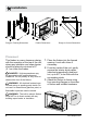
Installation K H I C A D F B Rough-In Framing Dimensions L J G E Firebox Dimensions Rough-In Corner Dimensions Placement This firebox is a zero clearance design, with the exception of the top of the unit, where any insulation and vapor barrier should be placed a minimum of 2" (5.1 cm) from the firebox. DANGER!: High temperatures may be generated under certain abnormal conditions. Do not partially or fully cover or obstruct the front of the firebox.
Electrical Bathroom Installation This built-in electric firebox must be protected by a GFI circuit when installed in an area where water is present. If the unit is installed using a receptacle, it must be readily accessible. This firebox is not watertight and must be installed as to prevent water from entering the unit. Install the unit away from showers, tubs, etc. Keep towels and other combustible materials 3 feet (0.9 m) away from the front of the unit.
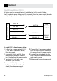
Electrical Direct Power Wiring (120 V) All wiring must be completed prior to installing the built-in electric firebox. FIREPLACE JUNCTION BOX Use 2-conductor wires with ground (3 wires total) from the power supply (breaker panel) to the junction box on the built-in electric firebox. WHITE - N WHITE - N BLUE - NH 120 V POWER SUPPLY RED - L2 BLACK - L1 BLACK - L1 GROUND - G GROUND - G BREAKER PANEL To install 120 V direct power wiring: 1. Pull out the 5 wires marked L1, L2, 5.
Electrical Direct Power Wiring (240 V) All wiring must be completed prior to installing the built-in electric firebox. FIREPLACE JUNCTION BOX Use 3-conductor wires with ground (4 wires total) from the power supply (breaker panel) to the junction box on the built-in electric firebox. WHITE - N WHITE - N BLUE - NH RED - L2 BLACK - L1 GROUND - G 240 V POWER SUPPLY RED - L2 BLACK - L1 GROUND - G BREAKER PANEL To install 240 V direct power wiring: 1. Pull out the 5 wires marked L1, L2, 5.
Electrical Wall Switch (120 V) ! NOTE: Use a single pole, single throw (On/Off) wall switch that is rated for a minimum of 15 A. Before installing the wall switch: • Connect a 2-conductor wire with ground (3 wires total) from the power supply panel to the main switch wall box. FIREPLACE JUNCTION BOX • Connect a 2-conductor wire with ground (3 wires total) from the main switch wall box to the junction box on the built-in electric firebox.
Electrical To install a 120 V wall switch: 1. Pull out the 5 wires marked L1, L2, 7. Secure the two remaining ground 2. Connect the N (white) and the NH 8. Insert all the wiring of the main N, NH, and G (black, red, white, blue, and green). (blue) wires from the built-in electric firebox to the N (white) from the power supply panel. 3. Terminate L2 (red) with a wire connector (not included). 4.
Electrical Wall Switch (240 V) ! NOTE: Use a double pole, single throw (On/Off) wall switch that is rated for a minimum of 15 A. Before installing the wall switch: • Connect a 3-conductor wire with ground (4 wires total) from the power supply panel to the main switch wall box. FIREPLACE JUNCTION BOX • Connect a 3-conductor wire with ground (4 wires total) from the main switch wall box to the junction box on the built-in electric firebox.
Electrical To install a 240 V wall switch: 1. Pull out the 5 wires marked L1, L2, 9. Connect the L1 wire from the power 2. Connect the N (white) wire from the 10.Connect the L2 (black) wire from N, NH, and G. (black, red, white, blue, and green). firebox to the N (white) wire from the main power wall switch by using a wire connector (not included). 3. Terminate NH (blue) with a wire connector (not included). 4.
Electrical M M 16 www.dimplex.
Operation Touch Panel and Remote Controls WARNING: The Revillusion® Built-in Electric Firebox must be installed properly before it is used. CAUTION: Except for installation and cleaning described in this manual, an authorized service representative should perform any other servicing. The manual controls for the Revillusion® Built-in Electric Firebox are located on the front panel. Touch an icon to activate. The selected setting displays on the left side of the panel.
Operation Icon Function Description Press to activate the current standby state (On/Off). • Standby State On Press to turn everything Off. Press again to activate the previous state. A Power/ Standby • Standby State Off Press to activate the previous state. --If the flame effect was On, the previous heat setting will be activated (On or Off). --If the flame effect was Off, the previous heat setting will be activated (High or Low). Press again to turn everything Off.
Operation Icon E F Function Color Themes 360o Light Description Press multiple times to change the flame base colors from Red to Blue to Off. (The first segment on the display will change from "r" to "b" to blank) This feature is active only when the flame effect is On. Press multiple times to change the LEDs on the sides and back of the unit from Midnight mode to white to yellow to red. (The middle segment on the display will change through 0 - 3 respectively.
Maintenance General Maintenance Remote Battery Replacement Inspect the built-in electric firebox regularly, depending upon conditions, and at a minimum yearly intervals. Remove dust and clean the logs, grate, and base as required. To replace the battery: 1. Push down on the battery cover located on the back of the remote control. Slide the battery cover open. 2. Install 3V (CR2032) Lithium battery in the battery holder. The positive (+) side of the battery faces up. 3. Close the battery cover.
Warranty Two Year Limited Warranty Products to which this limited warranty applies This limited warranty applies to your newly purchased Dimplex Revillusion® Built-in Electric Direbox Models: RBF30, RBF30WC, RBF36, RBF36WC, RBF36P, RBF36PWC, RBF42 and RBF42WC. This limited warranty applies only to purchases made in any province of Canada except for Yukon Territory, Nunavut, or Northwest Territories or in any of the 50 States of the USA (and the District of Columbia) except for Hawaii and Alaska.
Warranty when calling. Limited warranty service requires a proof of purchase of the product.
Warranty Glen Dimplex Americas may, in lieu of repair or replacement, choose to refund the purchase price for such product or part. The purchaser shall not be entitled to on-site or in-house services. The purchaser is responsible for all expenses incurred for repair or replacement of such product or part including, without limitation, all shipping costs and transportation costs to and from the authorized dealer’s or service agent’s business and all labour costs.
Technical Support Technical and troubleshooting support, as well as a list of replacement parts can be found on: www.dimplex.com/customer_support. 1-888-346-7539 | www.dimplex.com In keeping with our policy of continuous product improvement, we reserve the right to make changes without notice.