Service Manual Model RLG20 RLG25 Part Number 6909740159 6909760159 IMPORTANT SAFETY INFORMATION: Always read this manual first before attempting to service this log grate. For your safety, always comply with all warnings and safety instructions contained in this manual to prevent personal injury or property damage. Dimplex North America Limited 1367 Industrial Road Cambridge ON Canada N3H 4W3 1-888-346-7539 www.dimplex.
TABLE OF CONTENTS OPERATION. . . . . . . . . . . . . . . . . . . . . . . . . . . . . . . . . . . . . . . . . . . . . . . . . . . . . . . . . 3 RLG20. . . . . . . . . . . . . . . . . . . . . . . . . . . . . . . . . . . . . . . . . . . . . . . . . . . . . . . . . . . 3 RLG25. . . . . . . . . . . . . . . . . . . . . . . . . . . . . . . . . . . . . . . . . . . . . . . . . . . . . . . . . . . 4 MAINTENANCE . . . . . . . . . . . . . . . . .
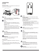
OPERATION RLG20 Manual Control The manual controls for the Revillusion are located on the right-front leg of the log grate. Power Press to turn the flame effect on and activate the previous heat setting (Off, Low, or High). Press again to put the unit in standby mode. Heat • Heat On Press to set the heat to Low (indicated by 1 short beep). Press again to set the heat to High (indicated by 2 short beeps). • Heat Off Press to turn heat Off (indicated by 1 long beep).
through its four brightness settings. RLG25 Manual Control The manual controls for the Revillusion are located on the right-front leg of the log grate. Power Press to activate the current standby state (On/Off). • Standby State On Press to turn everything Off. Press again to active the previous flame effect state. Power Press to turn the flame effect on and activate the previous heat setting (Off, Low, or High). Press again to put the unit in standby mode.
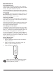
MAINTENANCE General Maintenance Inspect the log set regularly, depending upon conditions, and at a minimum yearly intervals. Remove dust and clean the logs, mat, grate, and base as required. Except for installation and cleaning described in this manual, an authorized service representative should perform any other servicing. WARNING: Disconnect power and allow heater to cool before attempting any maintenance or cleaning to reduce the risk of fire, electric shock, or injury.
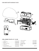
EXPLODED PARTS DIAGRAM - RLG20 4 3 6 2 5 10 7 1 8 9 11 12 REPLACEMENT PARTS LIST - RLG20 1. Logset, 20” . . . . . . . . . . . . . . . . . . . . . . . . . . . 0441910100RP 2. Flame LED Strip . . . . . . . . . . . . . . . . . . . . . . . 3001760100RP 3. Back Log . . . . . . . . . . . . . . . . . . . . . . . . . . . . 0441920100RP 4. Mirage™ Flame Panel. . . . . . . . . . . . . . . . . . 5902930100RP 5. Flicker Motor. . . . . . . . . . . . . . . . . . . . . . . . . . 2000500900RP 6.
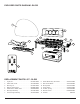
EXPLODED PARTS DIAGRAM - RLG25 4 3 2 5 7 1 6 12 8 11 9 10 14 13 REPLACEMENT PARTS LIST - RLG25 1. Logset, 25”. . . . . . . . . . . . . . . . . . . . . . . . . . . 0441940100RP 8. Heater-Blower Assy with Cutout. . . . . . . . . . . 2203730100RP 2. Flame LEDs, 4x1W . . . . . . . . . . . . . . . . . . . . 3001760200RP 9. Main Control Board . . . . . . . . . . . . . . . . . . . . 3001740200RP 3. Back Log, 25”. . . . . . . . . . . . . . . . . . . . . . . . . 0441950100RP 10.
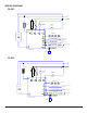
WIRING DIAGRAM RLG25 L N +T° +T° M CUTOUT BLOWER MOTOR FLICKER MOTOR M FLAME LIGHTS 120V / 12V ~ 4 x 1W LEDs AC / DC 4-7 x 0.20mA LED STRIP 4 PIECES LOGSET ASSEMBLY FLAME BASE COLOUR LIGHTS 4 x 0.20mA RGB STRIP 4-7 x 0.20mA LED STRIP 2 PIECES ASH MAT ASSEMBLY 360° COLOUR LIGHTS 6 x 0.20mA RGB HARNESS IR EYE/KEY BOARD CONTROL BOARD REMOTE RLG20 L N CUTOUT +T° +T° M BLOWER MOTOR FLICKER MOTOR M FLAME LIGHTS 3 x 1W LEDs 120V / 12V LOGSET ASSEMBLY 4-7 x 0.
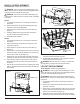
BACK LOG REPLACEMENT Figure 4 Tools Required: Philips head screwdriver WARNING: If the log grate was operating prior to servicing, allow at least 10 minutes for the heating elements to cool off to avoid accidental burning of skin. WARNING: Disconnect power before attempting any maintenance to reduce the risk of electric shock or damage to persons. RLG20 1. Lift the flame panel from the unit and put it aside in a safe place. 2.
5. Remove the two screws in the bottom of the second and fourth prongs of the grate to release the logs. 6. Trace the wire from the logs to the main control board and disconnect the wire, noting the location on the board. 7. Run the wire from the new logs, following the same path as the wire that was removed. Attach the new wire to the board. 8. Install the replacement logs and secure with the two screws that were previously removed. 9.
each corner on both ends. (Figure 4) 4. Gently tilt the unit onto the back and lower the bottom assembly so that the electrcial can be easily accessed. 5. Transfer the wire connectors from the terminals on the original board to the same location on the replacement board. ! NOTE: Use a flat head screwdriver to gently pry between the end of the connector and the remote control receiver to release the wires. 6.
Figure 8 Flicker Rod Flicker Motor 2. 3. 4. 5. 6. 7. 8. 9. 10. safe place. Remove the ember mat by disconnecting it from the right side of the unit. Remove the 3 screws along the bottom of the front and back of the bottom assembly and the four screws from each corner on both ends. (Figure 4) Gently tilt the unit onto the back and lower the bottom assembly so that the electrcial can be easily accessed.
Figure 9 Connecting Screws Plastic Spacer ! NOTE: Use a flat head screwdriver to gently pry between the end of the connector and the heater assembly to release the wires. WARNING: Ensure wires do not come in contact with moving parts by securing wires in wiring tie wraps.
TROUBLESHOOTING GUIDE PROBLEM CAUSE SOLUTION General Circuit breaker trips or fuse blows when unit is turned on Short in unit wiring. Trace wiring in unit. Improper circuit current rating Additional appliances may exceed the current rating of the circuit breaker or fuse. Plug unit into another outlet or install unit on a dedicated 15 amp circuit.
PROBLEM CAUSE SOLUTION Heater Heater is not turning Off Heater is not turning On Heater is turning off after a couple of minutes of operation Heater emits an odor Heater fan turns on but heater lacks heat Heating element is glowing red Heater fan runs continuously Improper operation Refer to Operation Section Defective main control board Replace main control board.