
Installation Guide

7201010001R12
Forced Air Heater
RFV-800 Series “D”
WARNING: Wiring procedures and connections should
be in accordance with the National Electric code and local
codes.
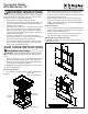
1. Remove heater from carton. The front grille and trim can
be lifted off assembly, and placed in carton to prevent
damage. Remove screws securing heater assembly to
the recess box and separate (Figure 1).
!
NOTE: Mount the heater a minimum of 12 inches (30.5
cm) from the nished oor.
Recessed Installation
2. The recess box provided with the heater is designed for
attachment between studs placed on 16” (40.6cm) cen-
tres. If different spacing exists, construct frame to suit
the box in order to avoid any vibration and noise caused
by loose mounting (Figure 2a).
3. Note orientation of box (“TOP” shown on recess box)
and secure to studs using four holes provided on side
anges, ensuring these anges are ush with nished
surface of wall (Figure 2b).
Surface Installation
2. Secure optional surface mount box (Part No. RFP8D) by
angling screws through holes provided in rear of surface
box into studs or nished surface.
3. Position recess box into surface box and secure with
four screws provided in parts bag of surface box.
Supply Wiring and Heater Installation
!
NOTE: All wiring must comply with National Electrical
Code and local codes.
Installation Instructions
IMPORTANT INSTRUCTIONS
When using electrical appliances, basic precautions should
always be followed to reduce the risk of re, electric shock
and injury to person, including the following:
1. Read all instructions before using this heater.
2. A heater has hot and arcing or sparking parts inside. Do
not use it in areas where gasoline, paint or ammable
liquids are used or stored.
3. This heater is hot when in use. To avoid burns, do not let
bare skin touch hot surfaces. If provided, use handles
when moving this heater. Keep combustible materials
such as: furniture, pillows, bedding, papers, clothes and
curtains away from heater.
4. To prevent a possible re, do not block air intakes or
exhaust in any manner. Do not use on soft surfaces like
a bed where openings may become blocked.
5. Do not insert or allow foreign objects to enter any venti-
lation or exhaust opening as this may cause an electric
shock or re, or damage the heater.
SAVE THESE INSTRUCTIONS
Figure 1
FRONT PANEL
(GRILLE) & TRIM FRAME
GROUND
SCREW
HEATER
ASSEMBLY
RECESS BOX
FINISHED WALL
SURFACE
SIDE FLANGES
15"
[38cm]
min. 12"
[30.5cm]
3 5/8"
[9cm]
14 1/4"
[36cm]
19 3/4"
[50cm]
7/8"[22mm] DIA
KNOCKOUT
FINISH FLOOR
19 3/4"
[50cm]
14 1/4"
[36cm]
min. 12"
[30.5cm]
Figure 2
A
B