CE INSTALLATION and OPERATING INSTRUCTIONS Brine-to-Water Heat Pump for Indoor Installation SI 7KS SI 9KS SI 11KS SI 14KS Order No.: 452231.67.
CONTENTS 1 PLEASE READ IMMEDIATELY 1.1 1.2 Important Information Legal Provisions and Directives 1.3 Energy-Efficient Use of the Heat Pump 2 PURPOSE OF THE HEAT PUMP 3 4 2.1 Application 2.2 Principle of Operation 3 BASELINE UNIT 4 4 ACCESSORIES 5 4.1 Brine Manifold 4.2 Brine Pressostat 5 TRANSPORT 5 6 INSTALLATION 6 6.1 General Information 6.2 Sound Emissions 7 MOUNTING 7.1 7.2 7.3 General Heating-Side Connection Connection on Heat Source Side 7.
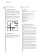
PLEASE READ IMMEDIATELY 1 READ IMMEDIATELY CAUTION! The supplied strainer is to be fitted in the heat source inlet of the heat pump in order to protect the evaporator against contamination. 1.1 Important Information CAUTION! The heat pump is not secured to the wooden pallet. CAUTION! Any work on the heat pump may only be performed by authorised and qualified customer service agents. CAUTION! CAUTION! CAUTION! The heat pump must not be tilted more than max. 45° (in either direction). 1.
PURPOSE OF HEAT PUMP BASELINE UNIT 2 PURPOSE OF THE HEAT PUMP 3 2.1 Application The brine-to-water heat pump is designed for use in existing or newly built heating systems. Brine is used as the heat carrier in the heat source system. Ground coils, ground collectors or similar systems can be used as the heat source. BASELINE UNIT The baseline unit consists of a heat pump of compact design, ready for connection.
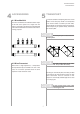
ACCESSORIES TRANSPORT 4 ACCESSORIES 5 TRANSPORT A lift truck is suited for transporting the unit on a level surface. If the heat pump needs to be transported on an uneven surface or carried up or down stairs, carrying straps may be used for this type of transport. These straps may be passed directly underneath the wooden pallet. 4.1 Brine Manifold The brine manifold ties the individual collector loops of the heat source system into a single main line which is connected to the heat pump.
INSTALLATION MOUNTING 6 INSTALLATION 6.1 General Information 7 As a rule, the unit must be installed indoors on a level, smooth and horizontal surface. The entire base frame should thereby make close contact with the surface in order to ensure adequate sound insulation. Failing this, additional sound insulation measures may become necessary. MOUNTING 7.
MOUNTING 7.4 Electrical Connection pump installations where a power failure cannot readily be detected (e.g. holiday houses), the heating circuit must contain a suitable antifreeze product. The following electrical connections must be established on the heat pump. The integrated expansion vessel has a capacity of 24 litres.This capacity is appropriate for buildings with a heated living space floor area of up to 200 m2.
COMMISSIONING CARE/CLEANING 8 Close all of the heating circuits that may also be closed during operation (depending on the type of heat pump usage) so that the least favourable operating state - with respect to the water flow rate - is achieved. Normally, these are the heating circuits of the rooms located on the south and west sides of buildings. At least one heating circuit must remain open (e.g. bathroom). COMMISSIONING 8.
CARE/CLEANING MALFUNCTIONS/TROUBLESHOOTING DECOMMISSIONING According to current knowledge, we recommend cleaning with a 5% phosphoric acid solution or, in the case that cleaning needs to be performed more frequently, with a 5% formic acid solution. 10 In either case, the cleaning fluid should be at room temperature. It is recommended that the heat exchanger be cleaned in the direction opposite to the normal flow direction. This heat pump is a quality product and is designed for trouble-free operation.
APPENDIX 12 APPENDIX 12.1 DIMENSIONED DRAWING 11 12.2 EQUIPMENT DATA 12 12.3 SCHEMATICS 12.3.1 12.3.2 12.3.3 12.3.4 Characteristics .. 7KS Characteristics .. 9KS Characteristics .. 11KS Characteristics .. 14KS 12.4 WIRING DIAGRAMS 12.4.1 12.4.2 12.4.3 12.4.4 Control .. 7KS to .. 14KS Load .. 7KS to .. 14KS Terminal Diagram .. 7KS to .. 14KS Legend .. 7KS to .. 14KS 12.5 HYDR. BLOCK DIAGRAM 21 12.6 EC DECLARATION OF CONFORMITY 22 12.
Heating circuit pressure gauge Brine circuit pressure gauge 11 Overpressure outlet Brine and heating circuits 3/4" hose Hot water flow Heat pump outlet 1 1/4" external thread Condensate outflow 12 mm outer diameter Connection of an additional expansion vessel, 3/4" external thread Common return flow HP inlet 1 1/4" external thread Overflow valve 1 1/4" external thread Heating water flow Heat pump outlet 1 1/4" external thread Heat source Heat pump outlet 1 1/4" external thread Heat source Heat pump
APPENDIX: 12.2 EQUIPMENT DATA Equipment Data EQUIPMENT DATA for Brine-to-Water Heat Pumps for Heating 1 TYPE AND COMMERCIAL DESCRIPTION 2 MODEL ..7KS ..9KS ..11KS ..14KS 2.1 2.2 Type compact compact compact compact Enclosure type acc. to EN 60 529 IP 20 IP 20 IP 20 IP 20 2.3 Installation site indoors indoors indoors indoors 3 PERFORMANCE DATA 3.1 Operating temperature limits: Heating water supply °C max. 55 max. 55 max. 55 max.
APPENDIX: 12.3 SCHEMATICS 12.3.1 Characteristics .. 7KS 12 Water outlet temperature in [°C] Heating capacity in [kW] 35 50 Conditions: Heating water flow rate Brine flow rate 10 0,6 m³/h 1,7 m³/h 8 6 4 2 0 -10 2,5 -5 0 5 10 Power consumption (incl.
APPENDIX: 12.3 SCHEMATICS 12.3.2 Characteristics .. 9KS 18 Water outlet temperature in [°C] Heating capacity in [kW] 16 Conditions: Heating water flow rate Brine flow rate 14 35 0,75 m³/h 2,3 m³/h 50 12 10 8 6 4 2 0 -10 3,5 -5 0 5 10 Power consumption (incl.
APPENDIX: 12.3 SCHEMATICS 12.3.3 Characteristics .. 11KS 20 Water outlet temperature in [°C] Heating capacity in [kW] 35 18 Conditions: Heating water flow rate Brine flow rate 16 50 1,0 m³/h 3,0 m³/h 14 12 10 8 6 4 2 0 -10 4 -5 0 5 10 Power consumption (incl.
APPENDIX: 12.3 SCHEMATICS 12.3.4 Characteristics .. 14KS 25 Water outlet temperature in [°C] Heating capacity in [kW] 35 50 20 15 10 Conditions: Heating water flow rate Brine flow rate 5 1,3 m³/h 3,5 m³/h 0 -10 -5 0 5 10 Power consumption (incl.
APPENDIX: 12.4 WIRING DIAGRAMS Mains power supply 12.4.1 Control .. 7KS to ..
Mains power supply Soft starter not available in brine-to-water unit 7KS APPENDIX: 12.4 WIRING DIAGRAMS 12.4.2 Load .. 7KS to ..
Mains power supply or 19 The function of the back-up heater can be selected Contact open = HP disabled Utility company disable contactor 2nd disable input Contact open = HP disabled Mains power supply to be field-connected, if required factory-wired APPENDIX: 12.4 WIRING DIAGRAMS 12.4.3 Terminal Diagram .. 7KS to ..
APPENDIX: 12.4 WIRING DIAGRAMS 12.4.4 Legend .. 7KS to ..
Heat pump with integr.
APPENDIX: 12.6 EC DECLARATION OF CONFORMITY EC Declaration of Conformity Declaration of Conformity The undersigned Glen Dimplex Deutschland GmbH Division Dimplex Am Goldenen Feld 18 D-95326 Kulmbach hereby confirm that the design and construction of the product(s) listed below, in the version(s) placed on the market by us, conform to the relevant requirements of the applicable EC directives.
Notes 23
Glen Dimplex Deutschland GmbH Division Dimplex Am Goldenen Feld 18 D-95326 Kulmbach Subject to technical modifications Fax +49 92 21/709-589 www.dimplex.