Owner’s Manual Solar Domestic Water Heating System Model ESSW2 ESDW2 ! arning: This system is designed to be used with Polypropylene Glycol as a W heat transfer liquid. Substitution of any other heat-transfer fluid can cause irreparable damage and create a health and safety hazard. NOTE: This manual should be kept in the same area as the system for reference purposes. IMPORTANT SAFETY INFORMATION: Always read this manual first before attempting to install or use this Solar Domestic Hot Water System.
Table of Contents Welcome & Congratulations . . . . . . . . . . . . . . . . . . . . . . . . . . . . . . . . . . . . . . . . . . . . . . . . . . . . . . . . 3 Important Instructions. . . . . . . . . . . . . . . . . . . . . . . . . . . . . . . . . . . . . . . . . . . . . . . . . . . . . . 4 Quick Reference Guide. . . . . . . . . . . . . . . . . . . . . . . . . . . . . . . . . . . . . . . . . . . . . . . . . . . . . . . . . . . . 5 General Operating Information. . . . . . . . . . . . . . . . . . . . . . . .
Welcome & Congratulations Dear Customer, Thank you very much for choosing the our Solar Domestic Hot Water System. We appreciate the choice of products you have had and we want to assure you that the Solar Hot Water System satisfy the highest performance, quality and reliability requirements. When correctly installed, commissioned, operated and maintained we are sure that you will enjoy many years of hot water from your Solar Hot Water System.
Important Instructions When using electrical appliances, basic precautions should always be followed to reduce the risk of fire, electric shock, and injury to persons, including the following: 1. Read all instructions before using this appliance. 2. Disconnect all power supplies before performing any cleaning, maintenance or relocation of the unit. 3. Do not modify any of the pumps. Use them only as described in this manual.
Quick Reference Guide Component Check List Kit Components Part Number Description ESSW2 Qty ESDW2 Qty DSCA-2M SOLAR COLLECTOR, DIMPLEX, FP BLUE-A, 2M 2 2 MK-DSCA MOUNTING KIT, 1 X DSCA 2 2 NA12142 FITTING, UNION, COMPRESSION 3/4” 2 2 254752 FITTING, ELBOW, COMPRESSION 3/4" THREADED 2 2 DSTA-200 STORAGE TANK, DIMPLEX, SOLAR HX, 53GAL/200L 1 1 9702900 EXPANSION TANK, SOLAR LOOP, 6.6GAL/25L 1 1 45111.5 NA CONTROLLER, MEIBES, SOLAR-A 1 1 8400410100 WIRE, CONNECTION, 6FT (1.
General Operating Information With the increasing concern for the health of our environment and the awareness to reduce our carbon emissions, the need to use alternative sources of energy is becoming more important. Using a Solar Domestic Hot Water System will assist with that and reduce your household heating costs throughout the year. The Dimplex® Solar Domestic Hot Water System has received US Energy Star Rating Certification.
General Operating Information Single Wall Heating System 5 3 1 1 4 4 3 2 8 7 80 2 0 60 40 20 40 8 20 4 6 0 0 120 14 10 0 0 120 14 10 60 80 To Pressure Relief Collection Tank 10 5 9 6 To 120V Power Supply Additional Temperature Probe Port (Optional) Outlet to Backup Heating System 10 Auxiliary Electrial Water Tank Inlet from Main Water Supply Mixing Valve 1. 2. 3. 4. 5.
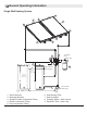
General Operating Information Double Wall Heating System 5 3 1 1 4 4 3 2 5 8 7 60 100 100 60 To Pressure Relief Collection Tank 80 80 4 0 40 40 20 10 20 8 120 140 2 6 120 140 9 To 120V Power Supply 2 6 0 8 60 40 20 40 120 140 20 To Pressure Relief Collection Tank 80 100 60 80 120 140 10 4 100 Auxiliary Electrial Water Tank Additional Temperature Probe Port (Optional) 12 Outlet to Backup Heating System 10 6 11 Inlet from Main Water Supply Mixing Valve 1. 2.
Site Selection and Preparation Prior to installation of a Domestic Solar Hot Water System Local Building Codes, Zoning Ordinances, Subdivision covenants and any other special regulations pertaining to the site should be consulted. To find out what’s needed for local compliance, contact the following: Your local jurisdiction’s zoning and building enforcement divisions • Briefly describe your intended construction, asking for other relevant ordinances/codes that might be in effect.
Site Selection and Preparation SYSTEM INSTALLATION AREA The location of the Solar Controller, pumping system and storage tanks can be planned in the same location as your current water heating system. The Dimplex Solar Hot Water System will require an area, in the same area as your current water heating system, which will allow for the 24” (61cm) diameter Solar Storage Tank with approximately 6” (15.2cm) diameter additional clearance, to enable easy access to monitor the system.
Site Selection and Preparation board or a “mounting wall”. For the double wall system installation the wall area required is approximately 4’ x 4’ (122 cm x 122 cm). For the single wall system installation the wall area required is approximately 2’ x 4’ (61 cm x 122 cm). CAUTION: Protection against auto-ignition of combustibles: Combustible materials used in soar equipment and adjacent structures shall not be exposed to an elevated temperature that could cause ignition.
Installation Instructions The Dimplex Solar Domestic Hot Water System is designed to be installed in series to your existing potable water heating system. arning: This system is to be installed in W accordance to Local Building Codes, Electrical Codes and National Roofing Contractors Association while following State/Provincial Health and Safety Standard practices. ! NOTE: The Overall layout of the system can be found in the General Operating Information Section of this manual.
Installation Instructions Figure 4 Figure 5 A Figure 6 B Figure 7 3 Figure 8 #10 Self Drilling Screw 3/8" x 2" Bolt " x 3 Lag Screw or 3 8" Bolt 8 3/8" Washer Clamp 3 3 8 8 " Lock Washer " EPDM Washer Bracket EPDM Gasket Flashing (Asphalt Roofs Only) Support Clamp Nut Clamp 3/8" Locknut Mounting Surface holes using a 5/16” drill bit. mark and drill 3/8” holes for the bolts to pass through. ! NOTE: The flashing can be used as a template 5.
Installation Instructions Figure 9 Sensor Well Detail A 1-4 for assembly of the top mounting assemblies. 11. Assemble the clamping assemblies (Figure 7) then insert them into the support brackets and tighten only to hold in place. 12. Place each Solar Collector on clamp assemblies, so that the sensor wells are located on the outside of the assembly and the clamps are securely resting on the brackets. 13.
Installation Instructions the threaded plugs in the unused ports. ! NOTE: There are two different thickness of shims provided to assist with ensuring that the collectors are level and connections are sealed properly. 14. Once the solar collectors are level and plumbed together, secure the bottom clamp assemblies, using #10 self drilling screws. (Figure 8) 15. Loosen the bolt in the bottom clamp and slide into groove of the solar collector and tighten to 35 lbs (15.9kg) of torque (Figure 9 - Detail A). 16.
Installation Instructions CAUTION: The pumping stations described are to be operated as described in these instruction with the recommended solar heat transfer liquid.
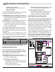
Installation Instructions Figure 12 80 80 60 0 0 60 10 10 4 0 10 40 40 20 8 0 0 20 2 6 120 1 4 120 1 4 4 2 6 0 8 10 60 40 20 0 120 1 4 0 120 1 4 40 0 10 0 20 80 10 60 80 ONLY USED IN ESDW2 MODEL GLYCOL LOOP DISTILLED WATER LOOP WIRING (POWER AND SENSORS) CAUTION: Hazards caused by neighboring building components, electrical, gas, water, or heating pipes must be prevented. 1. Select the installation location. Refer to Figure 12 for recommended layout.
Installation Instructions change. When deciding on the location for this component, the continuous fluctuations in volume/ weight needs to be taken into consideration, as the volume/weight of the tank will change throughout the day. CAUTION: To ensure the maximum life of the Solar Loop Expansion Tank do not use a solution with a higher concentration than 50% v/v polypropylene glycol.
Installation Instructions upon an assumed set of environmental conditions. Extended periods of cold weather, including ambient air temperatures above the specified limit, may cause freezing in exposed parts of the system.
Installation Instructions ! NOTE: Run electrical cables through the outer insulation access holes in the back insulation shell before mounting unit to wall. 4. Screw the pumping station through the back insulation shell and into the mounting holes. CAUTION: Connect the piping and ensure there are no leaks before making any electrical connections. 5.
Installation Instructions Figure 16 HXA Pumping Station - depending on the type of system you have installed - to the Solar Storage Tank (See Figures 11 or 14, and 15) 2. Install the temperature probe into the Temperature Sensor Well, at the bottom of the Solar Storage Tank. Insert the probe into the sensor well until it gently touches the end of the well.
Installation Instructions part using two latches. Pull the side pieces (cover plates) of the front of the housing outwards (Figure 16) to unlatch it and rotate upwards until the cover plate is opened. 6. Hang the Solar Controller onto two screws. Screw in the two lower screws. 7. Tighten all screws so the unit is secure on the wall. ! NOTE: Do not over tighten to avoid damage to the housing.
Commissioning arning: The initial start-up must be carried W out by a trained, qualified person and must be recorded in writing. The technical documentation must be kept with the equipment. CAUTION: The installer should ensure that the Solar Hot Water System is fully setup and functioning correctly before connecting the Solar Hot Water System to the Household water supply.
Commissioning Figure 19 1 2 Closed for Filling/Flushing 3 Open Normal Operation 3. Attach the Flush and Fill Pumping system to the Flush and Fill valve connections on the pumping station (Figure 11H). 4. Open Flush and Fill valves and pump a solution of non-foaming detergent (i.e. TSP, mixed to manufacturers directions) to flush the system of any dirt or debris. 5. Flush the system with clean water to remove any remaining solution or debris. 6. It is recommended that following the flush, 50 psi (3.
Commissioning cleaned to ensure that there is no cross contamination of the heat transfer liquids 1. On the HXA Pumping Station, rotate the Shutoff Ball valves (Figure 14D), to the Flushing & Filling Position (Position 2 - Figure 18). 2. Attach the Flush and Fill Pumping system to the Flush and Fill valve connections on the pumping station (Figure 14H). 3. Open Flush and Fill valves and pump a solution of non-foaming detergent (i.e.
Commissioning ! NOTE: The cold water supply line to the Solar Storage tank should be insulated with R-4.2, 1” (2.5cm) thick, for a minimum distance of 5’ (1.5m) or to the wall if it is less than 5’ (1.5m). 2. Install an isolation valve on the outlet of the Solar Storage Tank and add a Tee connection to the existing piping into the existing water heating system. 3. Install an Anti-Scalding valve on the outlet of the backup water heating systems before distribution throughout the house.
Operation arning: If the outdoor temperaW ture is expected to drop below the rated temperature range of the heat transfer liquid, drain the heat transfer liquid out of the system until the threat is no longer present. Solar Collectors There is no specific operator action required. Piping There is no specific operator action required. Pumping Station - Solar Loop-A arning: CHECK THAT ALL VALVES ARE W ORIENTED IN THE APPROPRIATE DIRECTION BEFORE STARTING THESE INSTRUCTIONS. see figures 18 & 19.
Operation ists. ! NOTE: If there is some air accumulated, open the air separator long enough to release the air. Then run the system for a little while and open it again to ensure that all of the air has been removed. • Temperature Gauges The system is equipped with two temperature gauges to monitor the temperature of the fluid travelling to and from the Solar Collector Panels.
Operation HXA Expansion Tank There is no specific operator action required. Figure 22 Solar Storage Tank Main Menu The Solar Storage Tank is equipped with a pressure relief valve. The activation pressure of the pressure relief valve is 29 psi (2 bar). Although the valve is set for 29 psi (2 bar) as the pressure release, the normal operation of the unit will be 14.5 psi (1 bar).
Operation Information Menu The Information Menu is the main menu for automatic regulation of Solar Hot Water System. It indicates current system values, the current system condition, any error messages and the number of operating hours. The table below indicates the readings in the Information Menu and whether they can be reset to assist in monitoring the system. Using the and buttons will allow the user to toggle through the displayed values. Indication Reset Description E.g.
Operation Description Solar Storage tank: Maximum Permissible temperature Indication Value range Default e.g. Settings 59-185°F 149°F max. 149°F (15-85°C) (65°C) Solar Storage tank: switch-on difference dT max 13°F 5-72 °F (3-40°C) 13 °F (7°C) Solar Storage tank: switch-off difference dT min. 5°F 4-30 °F (2-17°C) 5 °F (3°C) min. 100 30%-100% 100% Set the minimum pump capacity using the RPM control 100% = RPM control off To change the values: • Toggle through to the setting to be changed.
Operation set maximum temperature and the Solar Collector temperature exceeds the Solar Collector Protection setting (Line 1) the pumping stations will be switched on and will continue to run until the Solar Collector Temperature is 18°F (8°C) below the set maximum tank temperature. In this case, the Solar Storage Tank is charged up to 250°F (121°C) regardless of the set maximum temperature.
Maintenance Warning: Always completely disconnect the device from the power supply before performing maintenance or electrical work. The Solar Hot Water System should be monitored on at least a monthly basis, by checking system pressures, flows and temperatures to ensure that they are within normal operating range. These ranges can be found in the Operation Section of the manual and the Warranty Sheet.
Maintenance Sheets for pH range of solution. If the pH is outside of the range the solution should be replaced. ! NOTE: It is suggested that you change the distilled water at the same time that you change the Polypropylene Glycol, if equipped with a HXA Pumping Station. See Decommissioning Section for Polypropylene Glycol removal from system.
Maintenance arning: The water in both of the tanks is hot W enough that it could scald. 4. Close the Household Water isolation valve. 5. Turn on a hot water faucet to relieve pressure from the system. 6. Turn on another faucet, to allow air into the system. 7. Open the drain valve at the bottom of the Solar Storage Tank and drain approximately 2 gallons (7.5 liters) of water from the tank, so that when the rods are removed water does not splash out of the hole. 8. Unthread the Anode rod from top of tank.
Decommissioning arning: Always completely disconnect the W device from the power supply before performing maintenance or electrical work. Warning: The decommissioning must be carried out by a trained, qualified person and must be recorded in writing. The technical documentation must be kept with the equipment. The following instructions can be used for replacing Fluids, fixing failed components or disassembling the system.
Decommissioning Loop and HXA, or associated piping can be performed. 14. To empty the Solar Storage Tank, open the pressure relief valve on the top of the unit. 15. Open the drain valve at the bottom of the Solar Storage Tank and empty tank. 16. All of the sections of the Solar Hot Water System can now be disassembled.
Troubleshooting Problem Possible Cause Corrective Action The Solar Controller does not turn On 1. Unit is not plugged in. 2. Circuit breaker has tripped. 1. Plug unit in to outlet. 2. Check electrical panel. The Pump(s) do not turn On (but controller has power) 1. System does not need pumps On 2. Loose wiring symbol is turning. 1. Pumps should only be running if 2. Unplug unit and check pump connections inside of Solar Controller Backup heat System running when Solar system should be running 1.
Troubleshooting Solar Controller Errors Error representation on display Possible Cause Corrective Measures • • Sensor wire broken Defective sensor • • Check wire Check sensor resistance, if necessary replace sensor • • Short circuit in sensor wire Defective sensor • • Check wire Check sensor resistance, if necessary replace sensor Flashing Flashing Error representation No display function Possible Cause • • • Lost main power Controller internal safety fuse failed Appliance defect Corrective
Warranty DIMPLEX NORTH AMERICA LIMITED - LIMITED WARRANTY FOR SOLAR PRODUCTS Scope of limited warranty coverage Dimplex North America Limited’s (“Dimplex”) limited warranty to the original purchaser (“you”) of a product from the Dimplex product range set out below (each a “Product”) is as follows (the “Warranty”): Subject to the terms and conditions set out below, Dimplex warrants that new Products shall be free from defects in workmanship and materials under normal and proper usage, maintenance and service
Warranty Product; (vi) clouding or condensation; (vii) chemicals, fluids or liquids that are not authorized or otherwise approved by Dimplex for with the applicable Product; (viii) freezing temperatures and other natural or extreme weather conditions; and/or (ix) fire or other factors or circumstances that are outside of Dimplex’s control including, but not limited to, an Act of God.
Dimplex North America Limited 1367 Industrial Road Cambridge ON Canada N1R 7G8 © 2012 Dimplex North America Limited
Material Safety Data Sheet The Dow Chemical Company Product Name: DOWFROST* HD Heat Transfer Fluid, Dyed Issue Date: 08/12/2010 Print Date: 24 Nov 2010 The Dow Chemical Company encourages and expects you to read and understand the entire (M)SDS, as there is important information throughout the document. We expect you to follow the precautions identified in this document unless your use conditions would necessitate other appropriate methods or actions. 1.
Product Name: DOWFROST* HD Heat Transfer Fluid, Dyed Issue Date: 08/12/2010 Ingestion: Very low toxicity if swallowed. Harmful effects not anticipated from swallowing small amounts. Aspiration hazard: Based on physical properties, not likely to be an aspiration hazard. Effects of Repeated Exposure: In rare cases, repeated excessive exposure to propylene glycol may cause central nervous system effects. 3.
Product Name: DOWFROST* HD Heat Transfer Fluid, Dyed 6. Issue Date: 08/12/2010 Accidental Release Measures Steps to be Taken if Material is Released or Spilled: Small spills: Absorb with materials such as: Cat litter. Sawdust. Vermiculite. Zorb-all®. Collect in suitable and properly labeled containers. Large spills: Dike area to contain spill. See Section 13, Disposal Considerations, for additional information. Personal Precautions: Keep unnecessary and unprotected personnel from entering the area.
Product Name: DOWFROST* HD Heat Transfer Fluid, Dyed Issue Date: 08/12/2010 Engineering Controls Ventilation: Use local exhaust ventilation, or other engineering controls to maintain airborne levels below exposure limit requirements or guidelines. If there are no applicable exposure limit requirements or guidelines, general ventilation should be sufficient for most operations. Local exhaust ventilation may be necessary for some operations. 9.
Product Name: DOWFROST* HD Heat Transfer Fluid, Dyed Issue Date: 08/12/2010 Acute Toxicity Ingestion LD50, Rat, female > 20,300 mg/kg Dermal For the major component(s): LD50, Rabbit > 20,000 mg/kg Inhalation For the major component(s): No deaths occurred following exposure to a saturated atmosphere. LC50, 8 h, Vapor, Rat 4.1 mg/l Eye damage/eye irritation May cause slight temporary eye irritation. Corneal injury is unlikely.
Product Name: DOWFROST* HD Heat Transfer Fluid, Dyed Issue Date: 08/12/2010 NO CONTROL OVER THE MANAGEMENT PRACTICES OR MANUFACTURING PROCESSES OF PARTIES HANDLING OR USING THIS MATERIAL. THE INFORMATION PRESENTED HERE PERTAINS ONLY TO THE PRODUCT AS SHIPPED IN ITS INTENDED CONDITION AS DESCRIBED IN MSDS SECTION: Composition Information. FOR UNUSED & UNCONTAMINATED PRODUCT, the preferred options include sending to a licensed, permitted: Recycler. Reclaimer. Incinerator or other thermal destruction device.
Product Name: DOWFROST* HD Heat Transfer Fluid, Dyed Issue Date: 08/12/2010 California Proposition 65 (Safe Drinking Water and Toxic Enforcement Act of 1986) This product contains no listed substances known to the State of California to cause cancer, birth defects or other reproductive harm, at levels which would require a warning under the statute. Toxic Substances Control Act (TSCA) All components of this product are on the TSCA Inventory or are exempt from TSCA Inventory requirements under 40 CFR 720.