SIH 4ME SIH 6ME SIH 9ME SIH 11ME Installation and Operating Instructions Brine-to-Water Heat Pump for Indoor Installation 8/60183/0 ISSUE 2
Table of contents 1 Please Read Immediately.................................................................................................................2 1.1 1.2 1.3 1.4 2 Important Information................................................................................................................................. 2 Intended Use..............................................................................................................................................
1.4 1 Please Read Immediately 1.1 Important Information ATTENTION! The heat pump is not secured to the wooden pallet. 1.2 This device is only intended for use as specified by the manufacturer. Any other use beyond that intended by the manufacturer is prohibited. This requires the user to abide by the manufacturers product information. Please refrain from tampering with or altering the device. 1.3 ATTENTION! The heat pump must not be tilted more than 45° (in any direction).
2 2 2.1 Purpose of the Heat Pump Application The brine-to-water heat pump is to be used exclusively for the heating of heating water. It can be used in new or previously existing heating systems. Brine is used as the heat transfer medium in the heat source system. Borehole heat exchangers, ground heat collectors or similar systems can be used as the heat source. 2.2 Operating Principle The heat generated by the sun, wind and rain is stored in the ground.
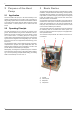
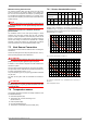
4.4 4 Accessories 4.1 Brine Circuit Manifold The brine circuit manifold merges the individual collector loops of the heat source system into a single main pipe which is connected to the heat pump. Integrated ball valves allow the individual brine circuits to be shut off for de-aeration purposes. 4.4 Thermal energy meter WMZ 4.4.1 General description The thermal energy meter (WMZ 25/32) is used for measuring the quantity of thermal energy supplied. It is available as an accessory.
5 5 Transport A lift truck is suited for transporting the unit on a level surface. Carrying straps may be used if the heat pump needs to be transported on an uneven surface or carried up or down stairs. These straps can be passed directly underneath the wooden pallet. ATTENTION! The heat pump is not secured to the wooden pallet. 6.2 Acoustic Emissions The heat pump operates silently due to efficient sound insulation.
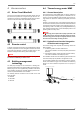
.4 The minimum heating water flow rate through the heat pump must be assured in all operating states of the heating system. This can be accomplished, for example, by installing either a dual differential pressureless manifold or an overflow valve. The procedure for adjusting an overflow valve is described in the Chapter Start-Up. NOTE The use of an overflow valve is only recommended for panel heating and a max. heating water flow of 1.3 m³/h. System faults may result if this is not observed.
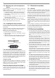
7.5 7.4.2 Mounting the external temperature sensor The temperature sensor must be mounted in such a way that all weather conditions are taken into consideration and the measured value is not falsified. On the external wall of a heated room used as living space, if possible on the north or north-west side of the building Do not install in a “sheltered position” (e.g.
8.3 6) The contactors mentioned above in points 3, 4 and 5 are installed in the electrical distribution system. The mains cables for the heating elements should be dimensioned and protected according to DIN VDE 0100. 7) All cables must be installed as permanent wiring. 8) The heat circulating pump (M13) is connected to terminals N and N1-J13/NO 5. 9) The DHW loading pump (M18) is connected to terminals N and N1-J13/NO 6. 10) The brine or well pump is connected to terminals N and N1J13/NO 3.
9 9 Maintenance and Cleaning 9.1 Maintenance To prevent faults due to sediment in the heat exchangers, care must be taken to ensure that no impurities can enter either the heat source system or the heating system. In the event that operating malfunctions due to contamination occur nevertheless, the system should be cleaned as described below. 9.
12 12 Device Information 1 Type and order code SIH 4ME 2 Design 2.1 Degree of protection according to EN 60 529 2.2 Installation Location 3 Performance data 3.1 Operating temperature limits: Heating water flow1 °C Brine (heat source) °C 3.
Appendix 1 Dimension Drawings .................................................................................................................... A-II 1.1 Dimension Drawing.................................................................................................................................A-II 2 Diagrams ...................................................................................................................................... A-III 2.1 2.2 2.3 2.4 3 Circuit Diagrams .............
1.1 1 Dimension Drawings 1.1 Dimension Drawing Appendix DSSUR[ 6XSSO\ FDEOHV +HDWLQJ ZDWHU IORZ +HDW SXPS RXWOHW ´ H[WHUQDO WKUHDG +HDW VRXUFH +HDW SXPS LQOHW ´ H[WHUQDO WKUHDG +HDW VRXUFH +HDW SXPS RXWOHW ´ H[WHUQDO WKUHDG www.dimplexrenewables.co.
2 2 Diagrams 2.
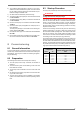
2.2 2.2 Characteristic Curves SIH 6ME +HDWLQJ FDSDFLW\ LQ >N:@ :DWHU RXWOHW WHPSHUDWXUH LQ >&@ &RQGLWLRQV +HDWLQJ ZDWHU IORZ UDWH %ULQH IORZ UDWH P K P K 3RZHU FRQVXPSWLRQ LQ >N:@ LQFO SRZHU LQSXW WR SXPS Appendix %ULQH LQOHW WHPSHUDWXUH LQ >&@ 3UHVVXUH ORVV LQ >3D@ (YDSRUDWRU %ULQH LQOHW WHPSHUDWXUH LQ >&@ &RHIILFLHQW RI SHUIRUPDQFH LQFO SRZHU LQSXW WR SXPS %ULQH IORZ UDWH LQ >P K@ 3UHVVXUH ORVV LQ >3D@ &RQGHQVHU %ULQH LQOHW WHPSHUDWXUH LQ >&@ www.
2.3 2.
2.4 2.4 Characteristic Curves SIH 11ME +HDWLQJ FDSDFLW\ LQ >N:@ :DWHU RXWOHW WHPSHUDWXUH LQ >&@ &RQGLWLRQV %ULQH IORZ UDWH P K P K Appendix +HDWLQJ ZDWHU IORZ UDWH %ULQH LQOHW WHPSHUDWXUH LQ >&@ 3RZHU FRQVXPSWLRQ LQ >N:@ LQFO SRZHU LQSXW WR SXPS 3UHVVXUH ORVV LQ >3D@ (YDSRUDWRU %ULQH LQOHW WHPSHUDWXUH LQ >&@ &RHIILFLHQW RI SHUIRUPDQFH LQFO SRZHU LQSXW WR SXPS %ULQH IORZ UDWH LQ >P K@ 3UHVVXUH ORVV LQ >3D@ &RQGHQVHU %ULQH LQOHW WHPSHUDWXUH LQ >&@ www.
3 3 Circuit Diagrams 3.
3.2 Load Appendix 3.2 www.dimplexrenewables.co.
3.3 3.
3.4 A1 A2 A3 A4 B2* B3* B4* C1 E10* F2 F3 F4 F5 J1...
4 4 Hydraulic Plumbing Diagram 4.
4.2 4.
5 5 Declaration of Conformity EC Declaration of Conformity GDC Group Limited, Millbrook House, Grange Drive, Hedge End, Southampton, Hants, SO302DF, United Kingdom Manufacturer: Glen Electric Ltd. Greenbank Industrial Est.. Rampart Road, Newry, Co. Down Hereby certified that the following device(s) complies/comply with the applicable EU directives. This certification loses its validity if the device(s) is/are modified.