SOLAR SOLC220 – Free standing kit Installation instructions Page 1 of 20 ST0117 - C – 08/09
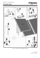
SOLC220 - Free standing kit SOLAR 0 Overall view Figure 1 – Overall view of installation method Page 2 of 20 ST0117 – C 08/09
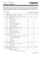
SOLC220 - Free standing kit 1 Contents SOLAR 0 OVERALL VIEW 2 1 CONTENTS 3 2 BEFORE YOU START 4 GENERAL COMPETENCE HEALTH AND SAFETY RISK ASSESSMENT TOOLS REQUIRED EARTHING AND LIGHTENING PROTECTION 4 4 4 5 5 5 3 SCOPE OF DELIVERY 6 4 PRODUCT FEATURES AND DESCRIPTIONS 7 5 COLLECTOR CONNECTIONS 8 5.1 SINGLE COLLECTOR VERTICAL CONNECTION 5.
SOLC220 - Free standing kit 2 Before you start SOLAR General Thank you for choosing a Dimplex product. We ensure you that every effort has been made at the design, manufacture and delivery stages to produce a product with superior quality. We will provide you with the best possible support throughout the product’s lifespan. As part of ongoing product development and improvement Dimplex reserves the right to undertake changes to the product without prior notice.
SOLC220 - Free standing kit Risk assessment SOLAR The compilation of a risk assessment is strongly recommended before installing the product. The following areas require particular consideration in addition to the information required by the Health and Safety at Work Act.
SOLC220 - Free standing kit SOLAR 3 Scope of delivery Please check the contents and the condition of your delivery before signing the delivery documentation against the content shown in Table 1 below and mark as appropriate. Contact your supplier immediately for any missing or damaged parts. Claims for missing of damaged parts after signing for the delivery documentation will not be accepted.
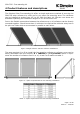
SOLC220 - Free standing kit 4 Product features and descriptions SOLAR The Dimplex Solar Free standing kit offers a simple and secure method of securing the SOLC220 solar collectors to a flat roof or any other flat mounting area. The collectors can be installed at angles from 45° to 60° with the basic kit. Shorter rear struts are available expanding the installation angles to 25° at the lower end. Due to the flexible connections between the collectors up to 10 collectors can be directly mounted together.
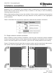
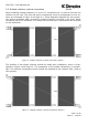
SOLC220 - Free standing kit 5 Collector connections SOLAR Because of its 4 connections, the collector offers a wide choice of connection options. Ensure that no part of the collector array or collector in the array is short circuited by following these instructions. When planning the collector array, the position of the various connection parts must be in accordance with the diagrams, also pay attention to the position of the highlighted sensor pockets.
SOLC220 - Free standing kit 5.2 Multiple collector vertical connection SOLAR When installing multiple collectors, (2 up to 10), component 10.1 is used to connect one collector to the next. The flow and return connections must be at diagonals to one another as illustrated in Figure 3 and Figure 4. These diagrams highlight the two connection options available when connecting multiple collectors vertically in an array.
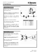
SOLC220 - Free standing kit 6 Installation SOLAR Step 1.1 Fixing - Determine the dimensions of the whole collector array and mark the position of the U-pieces (3.1). - Distance A applies to the spacing between the U-pieces of the basic kit, distance D to all extension kits. - Dimension B relates to the distance between the U-pieces of adjacent collectors. - Dimension C is fixed at 1140mm. - The measurements relate to the middle of the U-piece components.
SOLC220 - Free standing kit SOLAR Step 1.3 Fixing - Use the rawlplugs (3.4) and fasten the U-pieces (3.1) with washers (3.3) and bolts (3.2). - If U-rails are being used, also fasten these with washers (3.3) and bolts (3.2). Step 1.4 Fixing - Attach the supporting tube (2) to the rear U-pieces (3.1) with an M10 hexagonal bolt (3.6), spring washer (3.7) and hexagonal nut (3.8). - Put the protective cap (3.5) on the supporting tube.
SOLC220 - Free standing kit SOLAR Step 2.2 Collector - Preassemble four T-pieces (4.1) for each collector with M8 hexagonal bolts (4.2) on the square nuts in the slot on the rear of the collector (1). - To do so, align the first square nut with the help of the long side of the installation aid (4.4). - Attach the T-piece and screw in a hexagonal bolt. - Align the second square nut by turning the installation aid and screw in another hexagonal bolt. Step 2.
SOLC220 - Free standing kit SOLAR Step 2.4 Collector - Determine the definitive upper spacing of the T-pieces (4.1) on the collector. - The mounting angle is determined by the spacing H between the two Tpieces. - Screw the T-pieces tightly. - For mounting options 30°, 35° and 40° component 2.1 (rear strut 740mm long) must be used. Step 2.5 Collector - Punch the two drainage holes at each BOTTOM corner of the collector, according to how it is mounted, with the aid of a slotted screwdriver.
SOLC220 - Free standing kit SOLAR Step 2.6 Collector - Have the M10 hexagonal bolts (3.6), large spacer sleeves (3.9), spring washers (3.7) and M10 hexagonal nuts (3.8) ready for fastening the collector. - If laying the collector on the surface for a short time, it may be necessary to use an underlay to avoid damage to the frame. - The help of a second person is required to position the collector and fix it in place. The collector must NOT be rested on the back pane or the glass.
SOLC220 - Free standing kit SOLAR Step 2.7.1 Collector - Attach the collector (1) to the front Upieces (3.1). - To do so, position the collector with the help of a second person. - Attach the T-pieces (4.1) to the Upieces using M10 hexagonal bolts (3.6), large spacer sleeves (3.9), spring washers (3.7) and M10 hexagonal nuts (3.8). Step 2.7.2 Collector - Slowly tilt the collector (1) towards the supporting tubes (2). - Attach the T-pieces using M10 hexagonal bolts (3.6), large spacer sleeves (4.
SOLC220 - Free standing kit SOLAR Step 2.7.3 Connections - Fit the insert rings onto the corrugated interconnection component. - Ensure two insert rings are inserted into the 4th and 5th trough from both ends of the component. - The insert rings must be securely pressed together around the circumference of the corrugated pipe. - Coat the o-rings of the corrugated pipe compensators (6.1) with grease (5.5) and fit one of them in each of the connection of the pre-assembled collector.
SOLC220 - Free standing kit SOLAR Step 2.7.5 Collector - Preassemble the lower T-pieces to the U-pieces using M10 hexagonal bolts (3.6), large spacer sleeves (3.9), spring washers (3.7) and M10 hexagonal nuts (3.8). - Keep supporting the collector until all M10 hexagonal bolts have been attached. - Screw tight all M10 hexagonal bolts with spring washers and M10 hexagonal nuts. Step 3.1 Connections The remaining interconnections made, ensuring that; are - Insert rings (6.
SOLC220 - Free standing kit SOLAR Step 3.3 Connections - Coat in O-rings of the connection pipe (5.1) with the grease (5.5). - Position the insert rings (5.6) in the 4th and 5th trough of the corrugated pipe, counted from the end. - Next insert the connection pipe into the collector connection until the outer insert ring is flush with the outside of the collector tulip. Step 3.4 Connections - Pull clamps (5.
SOLC220 - Free standing kit SOLAR Step 4.1 Sensor - Carefully remove the grommet from the collector housing. - Slide the grommet over the temperature sensor (included with the solar controller). - Insert the temperature sensor fully into the immersion sleeve. Seal the collector frame using grommet. Ensure correct placement of the grommet. Step 5.1 - Please refer to the ‘On site guide’ for details on pressure testing, testing for leaks and proper maintenance of the system.
SOLC220 - Free standing kit 7 Operation SOLAR Although there are no operational components in the free standing kit, the fixings should be tightened and double checked prior to commissioning of the system. Please refer to the On Site Guide for guidance on how to commission and operate the solar system. 8 Maintenance Risk of scalding! Before carrying out any maintenance work on the system ensure that it is safe to do so. The solar system must be decommissioned before work can be carried out.