Luft/WasserWärmepumpe für Außenaufstellung Installation and Operating Instructions English Instructions d’installation et d’utilisation Français Montage- und Gebrauchsanweisung Air-to-Water Heat Pump for Outdoor Installation Bestell-Nr. / Order no. / No de commande : 452149.66.
Table of contents 1 Please Read Immediately .............................................................................................................E-2 1.1 Important Information.............................................................................................................................. E-2 1.2 Legal Regulations and Directives ........................................................................................................... E-2 1.3 Energy-Efficient Use of the Heat Pump .......
1 1 Please Read Immediately 1.1 Important Information ATTENTION! Any work on the heat pump may only be performed by authorised and qualified after-sales service technicians. ATTENTION! English The device is not suitable for operation with a frequency converter. ATTENTION! Never install the device in rooms in which there are any permanent ignition sources. ATTENTION! When transporting the heat pump, ensure that it is not tilted more than 45° (in any direction).
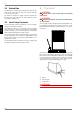
3.1 2 Purpose of the Heat Pump 2.1 Application The air-to-water heat pump is designed for use in existing or newly built heating systems. 3 Scope of Delivery 3.1 Basic Device The heat pump is of compact design and is supplied complete with the components listed below. R290 (propane) is used as refrigerant.
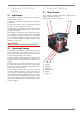
3.2 3.2 Switch Box The switch box is located in the heat pump. All electrical components are accessible after the front cover and the switch box cover have been removed. The switch box contains the supply connection terminals, the plug connector for the control line, as well as the power contactors and the soft starter unit. 3.3 Heat Pump Controller English Use the heat pump controller included in the scope of supply to operate the air-to-water heat pump.
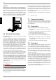
.2 Set-up 5.1 6 General Information 6.1 The heat pump is suited for outdoor installation. The device should always be installed on a permanently smooth, even and horizontal surface and must be aligned vertically. The entire frame should lie directly on the ground to ensure a good soundproof seal and to prevent the water-bearing components from becoming too cold. If this is not the case, additional insulation measures may be necessary.
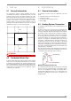
6.3 Antifreeze Manual drainage should be provided for heat pumps which are exposed to frost. The antifreeze function of the heat pump controller is active whenever the controller and the heat circulating pump are ready for operation. If the heat pump is taken out of service or in the event of a power failure, the system has to be drained, and if required, blown out, at three locations (see illustration).
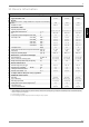
.2 From To Max. temperature spread between heating flow and return flow -20 °C -15 °C 4K -14 °C -10 °C 5K -9 °C -5 °C 6K -4 °C 0 °C 7K 1 °C 5 °C 8K 6 °C 10 °C 9K 11 °C 15 °C 10 K 16 °C 20 °C 11 K 21 °C 25 °C 12 K 26 °C 30 °C 13 K 31 °C 35 °C 14 K Any faults occurring during operation are also displayed on the heat pump controller and can be corrected as described in the operating instructions of the heat pump controller.
8.3 8.3 Cleaning the Air System Evaporator, ventilator and condensate outflow should be cleaned of contamination (leaves, twigs, etc.) before each new heating period. ATTENTION! Before opening the device, ensure that all circuits are isolated from the power supply. To prevent the evaporator and the condensate tray from being damaged, do not use hard or sharp objects for cleaning.
11 11 Device Information 1 Type and order code 2 Design 2.1 Degree of protection according to EN 60 529 for compact devices and heating components 2.2 Installation Location 3 Performance data 3.1 Operating temperature limits: 3.
Anhang / Appendix / Annexes 1 Maßbilder / Dimension Drawings / Schémas cotés................................................................... A-II 1.1 Maßbild / Dimension Drawing / Schéma coté LA 9PS............................................................................ A-II 1.2 Maßbild / Dimension Drawing / Schéma coté LA 12PS......................................................................... A-III 1.3 Maßbild / Dimension Drawing / Schéma coté LA 18PS..........................................
A-II &LUFXLW UHWRXU GH FKDXIIDJH HQWUpH GDQV 3$& Ö HQWUpH G¶HDX 5DFFRUG ILOHW H[W ³ +HDW UHWXUQ IORZ LQOHW LQ +3 Ö ZDWHU LQOHW &RQQHFWLRQ ³ H[WHUQDO WKUHDG +HL]XQJVUFNODXI (LQJDQJ LQ :3 Ö :DVVHUHLQWULWW $QVFKOXVV ´ $XHQJHZLQGH &LUFXLW DOOHU GH FKDXIIDJH VRUWLH GH 3$& Ö VRUWLH G¶HDX 5DFFRUG ILOHW H[W ³ ,QWURGXFWLRQ UDFFRUGHPHQW GH SXLVVDQFH 9 3( +] HW OLJQH GH FRPPDQGH +HDW IORZ RXWOHW IURP +3 Ö ZDWHU RXWOHW &RQQHFWLRQ ³ H[WHUQDO WKU
(FRXOHPHQW GHV FRQGHQVDWV +HDW UHWXUQ IORZ LQOHW LQ +3 &RQQHFWLRQ ³ H[WHUQDO WKUHDG 6ZLWFK ER[ DUHD IRU WKH HOHFWULF FRQQHFWLRQV +HDW IORZ RXWOHW IURP +3 &RQQHFWLRQ ³ H[WHUQDO WKUHDG ,QIHHG RU IHHGWKURXJK DUHD IRU ZDWHU FRQQHFWLRQ SLSHV KRVHV DQG HOHFWULF VXSSO\ OHDGV &RQGHQVDWH RXWIORZ +HL]XQJVUFNODXI (LQJDQJ LQ :3 $QVFKOXVV ´ $XHQJHZLQGH %HVFKULIWXQJVVWUHLIHQ 6FKDOWNDVWHQ HOHNWU $QVFKOXVVEHUHLFK +HL]XQJVYRUODXI $XVJDQJ DXV :3 $QVFKOXVV ´ $XHQJHZLQGH (LQ E]Z 'XUFKIKU
A-IV (FRXOHPHQW GHV FRQGHQVDWV 6ZLWFK ER[ DUHD IRU WKH HOHFWULF FRQQHFWLRQV +HDW IORZ RXWOHW IURP +3 &RQQHFWLRQ ³ H[WHUQDO WKUHDG ,QIHHG RU IHHGWKURXJK DUHD IRU ZDWHU FRQQHFWLRQ SLSHV KRVHV DQG HOHFWULF VXSSO\ OHDGV &RQGHQVDWH RXWIORZ %HVFKULIWXQJVVWUHLIHQ 6FKDOWNDVWHQ HOHNWU $QVFKOXVVEHUHLFK +HL]XQJVYRUODXI $XVJDQJ DXV :3 $QVFKOXVV ´ $XHQJHZLQGH (LQ E]Z 'XUFKIKUXQJVEHUHLFK IU :DVVHUDQVFKOXVVURKUH 6FKOlXFKH XQG (OHNWUR]XOHLWXQJHQ .
2.1 2 Diagramme / Diagrams / Diagrammes Kennlinien / Characteristic Curves / Courbes caractéristiques LA 9PS +HL]OHLVWXQJ LQ >N:@ +HDWLQJ FDSDFLW\ LQ >N:@ 3XLVVDQFH GH FKDXIIDJH HQ >N:@ :DVVHUDXVWULWWVWHPSHUDWXU LQ >&@ :DWHU RXWOHW WHPSHUDWXUH LQ >&@ 7HPSpUDWXUH GH VRUWLH GH O HDX HQ >&@ %HGLQJXQJHQ Â &RQGLWLRQV Â &RQGLWLRQV +HL]ZDVVHUGXUFKVDW] +HDWLQJ ZDWHU IORZ UDWH 'pELW G HDX GH FKDXIIDJH P K Anhang · Appendix · Annexes 2.
2.2 2.
2.3 Kennlinien / Characteristic Curves / Courbes caractéristiques LA 18PS +HL]OHLVWXQJ LQ >N:@ +HDWLQJ FDSDFLW\ LQ >N:@ 3XLVVDQFH GH FKDXIIDJH HQ >N:@ :DVVHUDXVWULWWVWHPSHUDWXU LQ >&@ :DWHU RXWOHW WHPSHUDWXUH LQ >&@ 7HPSpUDWXUH GH VRUWLH GH O HDX HQ >&@ %HGLQJXQJHQ Â &RQGLWLRQV Â &RQGLWLRQV +HL]ZDVVHUGXUFKVDW] +HDWLQJ ZDWHU IORZ UDWH 'pELW G HDX GH FKDXIIDJH P K Anhang · Appendix · Annexes 2.
A-VIII 7RXWHV OHV VHFWLRQV PP SRO SROH S{OHV VDQV IRQFWLRQ HQ FDV GH IRQFWLRQQHPHQW DYHF UpJXODWHXU GH SRPSH j FKDOHXU QR IXQFWLRQ LQ +3 FRQWUROOHU PRGH NHLQH )XQNWLRQ EHL :35 %HWULHE :lUPHSXPSHQUHJOHU 1 +HDW SXPS FRQWUROOHU 1 5pJXODWHXU GH SRPSH j FKDOHXU 1 SRO SROH S{OHV 3.
1HW] 0DLQV 5pVHDX Anhang · Appendix · Annexes 3.2 3( 9HUWHLOHU 3( GLVWULEXWRU 'LVWULEXWHXU 3( 3.
3.3 3.3 Anschlussplan / Circuit Diagram / Schéma électrique LA 9PS Anhang · Appendix · Annexes 6WHXHUOHLWXQJ Â &RQWURO OHDG Â /LJQH GH FRPPDQGH 1HW] Â 0DLQV Â 5pVHDX 6WHXHUOHLWXQJ Â &RQWURO OHDG Â /LJQH GH FRPPDQGH JH JQ \H JQ MD YH $GHU XQG 3LQQXPPHUQ :LUH DQG SLQ QXPEHUV 1XPpURV GH EULQV HW GH EURFKHV :lUPHSXPSHQUHJOHU 1 +HDW SXPS FRQWUROOHU 1 5pJXODWHXU GH SRPSH D FKDOHXU 1 $GHU [[ XQG 3LQQXPPHUQ :LUH [[ DQG SLQ QXPEHUV 1XPpURV GH EULQV [[ HW GH EURFKHV 9RUVLFKW .
3.4 3.
A-XII 7RXWHV OHV VHFWLRQV PP SRO SROH S{OHV VDQV IRQFWLRQ HQ FDV GH IRQFWLRQQHPHQW DYHF UpJXODWHXU GH SRPSH j FKDOHXU QR IXQFWLRQ LQ +3 FRQWUROOHU PRGH NHLQH )XQNWLRQ EHL :35 %HWULHE :lUPHSXPSHQUHJOHU 1 +HDW SXPS FRQWUROOHU 1 5pJXODWHXU GH SRPSH j FKDOHXU 1 SRO SROH S{OHV 3.5 $OO FURVV VHFWLRQV PP Anhang · Appendix · Annexes $OOH 4XHUVFKQLWWH PP 6WHXHUOHLWXQJ [ PP &RQWURO OHDG [ PP /LJQH GH FRPPDQGH [ PP 3.
1HW] 0DLQV 5pVHDX Anhang · Appendix · Annexes 3.6 3( 9HUWHLOHU 3( GLVWULEXWRU 'LVWULEXWHXU 3( 3.
3.7 3.7 Anschlussplan / Circuit Diagram / Schéma électrique LA 12PS Anhang · Appendix · Annexes 6WHXHUOHLWXQJ Â &RQWURO OHDG Â /LJQH GH FRPPDQGH 1HW] Â 0DLQV Â 5pVHDX 6WHXHUOHLWXQJ Â &RQWURO OHDG Â /LJQH GH FRPPDQGH JH JQ \H JQ MD YH $GHU XQG 3LQQXPPHUQ :LUH DQG SLQ QXPEHUV 1XPpURV GH EULQV HW GH EURFKHV :lUPHSXPSHQUHJOHU 1 +HDW SXPS FRQWUROOHU 1 5pJXODWHXU GH SRPSH D FKDOHXU 1 $GHU [[ XQG 3LQQXPPHUQ :LUH [[ DQG SLQ QXPEHUV 1XPpURV GH EULQV [[ HW GH EURFKHV 9RUVLFKW .
3.8 3.
A-XVI 7RXWHV OHV VHFWLRQV PP SRO SROH S{OHV VDQV IRQFWLRQ HQ FDV GH IRQFWLRQQHPHQW DYHF UpJXODWHXU GH SRPSH j FKDOHXU QR IXQFWLRQ LQ +3 FRQWUROOHU PRGH NHLQH )XQNWLRQ EHL :35 %HWULHE :lUPHSXPSHQUHJOHU 1 +HDW SXPS FRQWUROOHU 1 5pJXODWHXU GH SRPSH j FKDOHXU 1 SRO SROH S{OHV 3.9 $OO FURVV VHFWLRQV PP Anhang · Appendix · Annexes $OOH 4XHUVFKQLWWH PP 6WHXHUOHLWXQJ [ PP &RQWURO OHDG [ PP /LJQH GH FRPPDQGH [ PP 3.
1HW] 0DLQV 5pVHDX 3( 9HUWHLOHU 3( GLVWULEXWRU 'LVWULEXWHXU 3( Anhang · Appendix · Annexes 3.10 3.
3.11 3.
3.
4 4 Hydraulische Prinzipschemen / Hydraulic Plumbing Diagram / Schéma hydraulique 4.
4.2 Monoenergetische Anlage und Warmwasserbereitung / Mono Energy System and Domestic Hot Water Preparation / Installation monoénergétique et production d’eau chaude Anhang · Appendix · Annexes 4.
4.3 4.
4.
5 5 Konformitätserklärung / Declaration of Conformity / Déclaration de conformité Anhang · Appendix · Annexes A-XXIV
Glen Dimplex Deutschland GmbH Geschäftsbereich Dimplex Am Goldenen Feld 18 D-95326 Kulmbach Irrtümer und Änderungen vorbehalten. Subject to alterations and errors. Sous réserve d’erreurs et modifications. +49 (0) 9221 709 565 www.dimplex.