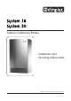
System 18 System 30 System Condensing Boilers Installation and Servicing Instructions These instructions should be left with the user © Dimplex Boilers 2008
GAS COUNCIL NUMBERS Natural Gas Dimplex System 18 - Gas Council Appliance No: 41 149 02 Dimplex System 30 - Gas Council Appliance No: 41 149 01 APPROVED PRODUCT 2 © Dimplex Boilers 2008
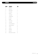
CONTENTS SECTION DESCRIPTION PAGE 1.0 Introduction 4 2.0 Boiler Layout 7 3.0 Boiler Operation 8 4.0 Technical Data 9 5.0 Dimensions 10 6.0 System Details 11 7.0 Site Requirements 13 8.0 Flue options 17 9.0 Installation 20 10.0 Commissioning 24 11.0 Service Mode 26 12.0 Servicing & Maintenance 27 13.0 Changing Components 30 14.0 Electrical 38 15.0 Spare Parts 39 16.0 Fault Finding 40 17.0 Benchmark 42 18.
1.0 1.1 INTRODUCTION BUILDING REGULATIONS AND BENCHMARK CHECKLIST 1.2 INSTALLATION, COMMISSIONING, SERVICE & REPAIR Building Regulations (England & Wales) require notification of the installation of a heating appliance to the relevant Local Authority Building Control Department. This appliance must be installed in accordance with the manufacturer’s instructions and the regulations in force. Read the instructions fully before installing or using the appliance.
1.0 1.3 INTRODUCTION LEGISLATION The appliance is suitable only for installation in GB and IE and should be installed in accordance with the rules in force, and only used in a suitably ventilated location. In GB, the installation must be carried out by a CORGI Registered Installer. It must be carried out in accordance with the relevant requirements of the: • Gas Safety (Installation & Use) Regulations.
1.0 1.4 INTRODUCTION SAFE MANUAL HANDLING 1. The boiler should be handled and lifted by two people. Wear appropriate Personal Protection Equipment e.g. protective gloves, safety footwear etc. Plan your route to minimise the number of turns needed to handle/lift the boiler. 2. Where possible transport the boiler using a sack truck or other suitable trolley. Try to avoid steps, wet or slippery surfaces, unlit areas etc. and take special care on ladders/into lofts. 3.
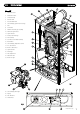
2.0 BOILER LAYOUT 2.1 KEY 1. Expansion Vessel 2. Automatic Air Vent 3. Circulation Pump 4. Drain Off Point 5. Pressure Relief Valve 6. Central Heating System Pressure Gauge 7. PCB 8. Control Box 9. Flexible condensate pipe assembly 22 21 1 26 27 10. Flame Sensing Electrode 18 11. Spark Electrode 12. Primary Heat Exchanger 13. Fan Assembly 10 14. Gas Valve & Swirl Plate Assembly 15. Reset Button 17 16. Central Heating Temperature Control 17.
3.0 3.1 BOILER OPERATION CENTRAL HEATING 1. With a demand for heating, the pump, circulates water through the primary circuit. 2. Once the main burner ignites the fan speed controls the gas rate to maintain the heating temperature measured by the temperature sensors. 3. When the demand is satisfied the burner is extinguished and a 5 minute delay occurs before the burner will re-light (anticycling), the pump continues to run for a period of 2 minutes (Pump Overrun). 3.2 FROST PROTECTION MODE 1.
4.0 4.
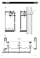
5.0 DIMENSIONS Fig. 4 264mm 182mm 185mm Tube Ø 100mm 148mm 150mm 94mm 796mm 446mm 333mm Fig.
6.0 6.1 SYSTEM DETAILS INFORMATION 1. The Dimplex System Boiler is a ‘Water Byelaws Scheme Approved Product’. Reference to the Water Research Council publications, ‘Water fittings and materials directory’ and ‘Water supply byelaws guide’ give full details of byelaws and the IRNs. 6.2 HEATING CIRCUIT 1. The appliance is suitable for fully pumped SEALED SYSTEMS ONLY. Treatment of Water Circulating Systems Failure to flush and add inhibitor to the system will invalidate the appliance warranty.
6.0 SYSTEM DETAILS Fig. 6 6.4 SYSTEM FILLING AND PRESSURISING 1. A filling point connection on the central heating return pipework must be provided for initial filling and pressurising and subsequent topping up of the system. A filling loop is provided loose with the boiler Double Stop Check Valve Valve 2. The filling method adopted must comply with all relevant water supply regulations and use approved equipment. 3. Further details are given in; for GB: Guidance G24.2 and recommendation R24.
7.0 7.1 SITE REQUIREMENTS LOCATION Window Recess Zone 2 1. The boiler may be fitted to any suitable wall with the flue passing through an outside wall or roof and discharging to atmosphere in a position permitting satisfactory removal of combustion products and providing an adequate air supply. The boiler should be fitted within the building unless otherwise protected by a suitable enclosure i.e. garage or outhouse. (The boiler may be fitted inside an unvented cupboard - see section 7.3).
7.0 7.3 SITE REQUIREMENTS VENTILATION OF COMPARTMENTS 1. Where the appliance is installed in a cupboard or compartment, no air vents are required. Where an open flued system is used - Flue kit E (B23 classification) then an air vent communicating directly with outside air must be provided in the same room or internal space of the flue duct air inlet.
7.0 7.6 SITE REQUIREMENTS CONDENSATE DRAIN NOTE: The appliance is fitted with a trap the depth of which is >= 75mm, therefore no other traps are required in the condensate run. Termination to an internal soil and vent pipe The condensation discharge pipe must not rise at any point along its length. There MUST be a fall of AT LEAST 2.5° (50mm per metre) along the entire run. 1. The condensate outlet will accept 21.
7.0 7.7 SITE REQUIREMENTS FLUE Adjoining Properties Boundary Line 1. This high efficiency boiler will discharge a plume of water vapour from the flue. This should be considered when siting the flue terminal. 300mm Min 300mm Min 2. The following guidelines indicate the general requirements for siting balanced flue terminals. For GB recommendations are given in BS 5440 Pt 1. For IE recommendations are given in the current edition of I.S. 813 “Domestic Gas Installations”. 3.
8.0 FLUE OPTIONS Chimney flue liner kit - Part no. 956082 8.1 CONCENTRIC AIR/FLUE DUCT SPECIFICATIONS Vertical flue kit - Part no. 956081 The different flue applications shown in Fig. 20 are available as kits comprising the connecting parts to the appliance and end terminal. Flue extension ducts and extension elbows are available as accessories. Vertical flue kit - Part no. 956081 Raised external flue outlet kit - Part no. 956084 Vertical flue kit - Part no.
8.0 8.4 FLUE OPTIONS Total Equivalent Lengths for Concentric (60/100mm) flue systems Component Equivalent length in metres Part number 45° Bend 93° Bend 0.5m Extension 1.0m Extension Support Bracket 0.5m 1.0m 0.5m 1.0m N/A 956090 - 2 off 956091 956092 956093 840517 8.5 93° Bend 45° Bend 0.5m Extension 1.0m Extension Fig. 23 Support Bracket Kit C Horizontal Anti-Plume Flue Kit (C13) - Part No.
8.0 FLUE OPTIONS 8.8 Kit E Chimney Flue Liner Kit (B23) - Part no. 956082 Chimney flue liner kit - Part no. 956082 Chimney terminal Note: Dimplex System 18 and 30: Maximum flue length = 30m. Minimum length for all Dimplex System boilers = 5m. The chimney must be swept and cleared of any debris and obstructions. This kit is suitable for open flue application in accordance with BS5440 parts 1 & 2 where a room sealed flue installation is impractical.
9.0 9.1 INSTALLATION UNPACKING & INITIAL PREPARATION The gas supply, gas type and pressure must be checked for suitability before connection 1. Remove the top cardboard tray from the carton. 2. The wall fixing jig is packed in its own cardboard sleeve. Carefully slide this out of the carton. 3. To avoid scratching the boiler outercase, keep the outer carton in place. 4. After reviewing the site requirements (see Section 7.
9.0 9.2 INSTALLATION Front Panel Retaining Stud FITTING THE BOILER X2 1. Remove the sealing caps from the boiler connections. NOTE: A small amount of water may drain from the boiler once the caps are removed. 2. Check the sealing washers are located correctly in the taps on the wall jig. 3. Lift the boiler as indicated by the shaded areas. The boiler should be lifted by TWO PEOPLE. Engage the slots at the top rear of the boiler on the wall plate (Fig. 31) (see Safe Manual Handling page 6). 4.
9.0 9.5 INSTALLATION FITTING THE FLUE HORIZONTAL TELESCOPIC FLUE 1. For correct flue installation please refer to the installation instructions that are provided with the individual flue kit as described in sections 7 & 8. 2. Measure the required flue length as shown in Fig. 34. Refer to section 8 to determine whether any extension kits are required. Installations using only the standard ducts or standard ducts with straight extensions are described in this section.
9.0 9.6 INSTALLATION MAKING THE ELECTRICAL CONNECTIONS The boiler is fitted with a 1.5m length of 3 core cable. This can be connected to the fused 3A 230V 50Hz supply. To connect an external control proceed as follows:1. Lower the drop down door. 2. Remove the two screws holding the controls box and ease the box away from the boiler. The electrical connections are made at the left hand side on the rear of this box. 3. Slacken the cable clamp on the terminal block (Fig. 36).
10.0 10.1 COMMISSIONING COMMISSIONING THE BOILER Air Vent IMPORTANT: The air vent on top of the boiler must be OPEN when filling the system. Attach a tube to the air vent to safely collect any excess water (Fig. 38). Gas Tightness 1. Ensure the gas service cock on the boiler is turned on (Fig. 40). The entire gas installation must be tested for gas tightness and purged in accordance with BS6891. Tube Fig. 38 2. Open the service cocks to the CH flow and CH return supplies. 3.
10.0 10.2 COMMISSIONING FACTORY SETTINGS NOTE: This boiler is supplied factory set for operation on natural gas. No further adjustments of the air/gas ratio valve or measurement of the combustion performance are necessary at the time of installation and commissioning. This is provided the appliance has been installed according to these instructions and the inlet gas pressure is within our specification. 10.
11.0 SERVICE MODE NOTE: Service Mode automatically stops after 10 minutes and the boiler returns to normal operation. 2 3 1 11.1 TO SET THE BOILER AT MINIMUM GAS RATE 0 4 bar 1. Turn the CH knob fully clockwise - Note the knob will turn past the maximum temperature mark (Fig. 45). 2. The CH light will flash continuously - the boiler is now running at minimum rate. 11.2 TO SET THE BOILER AT MAXIMUM GAS RATE 1. Set the boiler into Service Mode at Minimum Rate. 2.
12.0 12.1 SERVICING AND MAINTENANCE ROUTINE SERVICING AND ALL MAINTENANCE THAT INVOLVES THE EXCHANGE OF PART OF THE COMBUSTION CIRCUIT 1. During routine servicing, e.g. an annual service check, and after all maintenance that involves the exchange of parts of the combustion circuit, we recommend that (in this order) the integrity of the full flue system and combustion circuit seals, the inlet gas pressure, gas rate and combustion performance is verified.
12.0 12.2 SERVICING AND MAINTENANCE COMBUSTION CHECKS COMBUSTION CHECKS AT MAXIMUM RATE 9. Set the boiler to Maximum gas rate. 10. Check the Carbon Monoxide (CO) and Carbon Dioxide (CO2) readings are within the range quoted in the tables opposite (Table 2). 11.
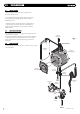
12.0 12.1 SERVICING AND MAINTENANCE ANNUAL SERVICING Fig. 49 8. Remove the two screws securing the front panel to the underside of the boiler. Lift the panel upwards off its retaining studs on top of the appliance. Front Panel Retaining Stud X2 9. Disconnect the two leads to the fan and one lead to the gas valve. 10. Undo the nut on the gas inlet pipe to the valve and retain the sealing washer. 11. Remove the four nuts holding the burner door plate and remove the valve and fan assembly (Fig. 51). 12.
13.0 CHANGING COMPONENTS IMPORTANT: When changing components ensure that both the gas and electrical supplies to the boiler are isolated before any work is started. See Section 12 : “Annual Servicing” for removal of case, panel, door etc. 13.1 IGNITER 1. Disconnect the two feed wires, earth wire and electrode lead noting their positions (Fig. 53). 2. Undo the two screws securing the igniter to its bracket and remove the igniter. Reassemble in reverse order. 13.2 SPARK AND SENSING ELECTRODES 1.
13.0 13.3 CHANGING COMPONENTS GAS VALVE AND FAN 1. Disconnect the two leads to the fan and one lead to the gas valve. 2. Undo the nut on the gas inlet pipe to the valve and retain the sealing washer. 3. Remove the three securing screws holding the air/gas Channel to the burner door plate and remove the valve and fan assembly (Fig. 57). 4. Remove the three screws holding the valve and swirl plate to the fan adaptor plate. NOTE: Mark on the adaptor plate which holes are being used by the screws.
13.0 13.4 CHANGING COMPONENTS Insulation BURNER 1. Remove the valve and fan assembly as described in Section 13.3. Burner Door 2. Examine the gasket and replace if necessary. 3. Undo the four nuts securing the burner door and remove from the heat exchanger. 4. Slowly withdraw the burner from the burner plate taking care not to damage the insulation (Fig. 58). Gasket 5. Reassemble in reverse order. Fig. 58 13.5 INSULATION Burner 1. Remove the electrode leads, noting their positions.
13.0 13.6 CHANGING COMPONENTS FLUE/HEAT TEMPERATURE THERMOSTAT ‘O’ Ring 1. Disconnect the electrical plug. 2. Turn the sensor 90° anticlockwise to remove - it is a bayonet connection (Fig. 60). Thermal Fuse 3. Reassemble in reverse order. 13.7 Flue/Heat Temperature Thermostat Fig. 60 THERMAL FUSE 1. The thermal fuse is non-changeable. If the fuse fails contact Dimplex Technical Department. 13.8 CENTRAL HEATING FLOW TEMPERATURE THERMISTOR 1. Disconnect the electrical plug. 2.
13.0 13.10 CHANGING COMPONENTS PUMP - HEAD ONLY 1. Drain the primary circuit and disconnect the wiring connector from the pump head. 2. Remove the four socket head screws securing the pump head to the body and draw the head away (Fig. 62). 3. A replacement Grundfos 15-60 head can now be fitted (Fig. 62)(Part No: 500672). 4. Reassemble in reverse order. Fig. 62 5. Replace the wiring connector into the socket on the pump head. 13.11 HYDROBLOCK 1. Drain the primary circuit. 2.
13.0 13.12 CHANGING COMPONENTS AUTOMATIC AIR VENT Automatic Air Vent 1. Drain the primary circuit and rotate the automatic air vent 1 /4 turn and remove from the pump body. 2. Examine the ‘O’ ring seal, replacing if necessary, and fit it to the new automatic air vent. ‘O’ Ring 3. Reassemble in reverse order. 13.13 PRESSURE GAUGE 1. Drain the primary circuit and undo the nut on the pressure gauge capillary. 2. Examine the ‘O’ ring seal, replace if necessary. 3. Unclip the facia from the control box 4.
13.0 CHANGING COMPONENTS Vessel Connection Pipe 13.16 EXPANSION VESSEL 1. Drain the primary circuit and undo the nut on the vessel connection pipe. 2. Remove the two screws holding the retaining bracket and remove the bracket (Fig. 67). Fig. 67 3. Carefully slide out the vessel from the boiler. Retaining Bracket 4. Reassemble in reverse order. Expansion Vessel 13.17 MAIN HEAT EXCHANGER 1. Drain the primary circuit. 2. Remove the electrode leads, noting their positions as described in section 13.2.
13.0 13.18 CHANGING COMPONENTS PCB Control Box 1. Ensure supply voltage is fully isolated. 2. Undo the screws holding the control box and gently ease the box forward (Fig. 69). 3. Locate the retaining barbs on the top of the fascia and unclip them from the control box. PCB Retaining Barbs Pressure Gauge 4. Unclip the PCB from the plastic control box. 5. Note the positions of all the connections on the PCB and disconnect them. (DO NOT REMOVE THE YELLOW BCC (Fig. 69)) 6.
14.0 14.1 ELECTRICAL ILLUSTRATED WIRING DIAGRAM Key - Cable Colours g y b r bk o g/y br gr w BOILER CHIP CARD BCC (IF FITTED) 8 FAN CONTROL 8 FLUE FLUE TEMP THERMISTER (5K NTC) 6 FLOW N.T.C. 6 RETURN N.T.C.
15.0 15.
16.0 FAULT FINDING Before checking for a fault condition carry out electrical checks to ensure the boiler has Earth continuity, correct polarity and Live and Neutral connections have no short circuit. 16.1 BASIC CHECKS 1. The mains electrical supply to the boiler and system controls are turned on. 2. The gas service cock is open. 3. External controls are calling for heat. 4. The system is filled with water and is correctly pressurized. 16.
16.0 FAULT FINDING DESCRIPTION OF CAUSES ACTIONS 1 Overheated appliance – Water temperature greater than 105°C. This causes a Non volatile lockout requiring a manual reset. Check for power failure Check Pump operation Check there is no air in Heat exchanger and check system bypass Check Temperature thermistors are located on pipe work correctly Check resistance of thermistors 4 No Flame –No flame signal on ignition. The boiler makes up to 5 ignition attempts on loss of flame signal.
17.0 BENCHMARK GAS BOILER SYSTEM COMMISSIONING CHECKLIST This Commissioning Checklist is to be completed in full by the competent person who commissioned the boiler as a means of demonstrating compliance with the appropriate Building Regulations and then handed to the customer to keep for future reference. Failure to install and commission this equipment to the manufacturer’s instructions may invalidate the warranty but does not affect statutory rights.
17.0 BENCHMARK SERVICE RECORD It is recommended that your heating system is serviced regularly and that the appropriate Service Record is completed. Service Provider Before completing the appropriate Service Record below, please ensure you have carried out the service as described in the manufacturer’s instructions. Always use the manufacturer’s specified spare part when replacing controls.
17.0 BENCHMARK MAINS PRESSURE HOT WATER STORAGE SYSTEM COMMISSIONING CHECKLIST This Commissioning Checklist is to be completed in full by the competent person who commissioned the storage system as a means of demonstrating compliance with the appropriate Building Regulations and then handed to the customer to keep for future reference. Failure to install and commission this equipment to the manufacturer’s instructions may invalidate the warranty but does not affect statutory rights.
17.0 BENCHMARK SERVICE RECORD It is recommended that your hot water system is serviced regularly and that the appropriate Service Record is completed. Service Provider Before completing the appropriate Service Record below, please ensure you have carried out the service as described in the manufacturer’s instructions.
17.0 BENCHMARK VENTED CYLINDER COMMISSIONING CHECKLIST This Commissioning Checklist is to be completed in full by the competent person who commissioned the cylinder as a means of demonstrating compliance with the appropriate Building Regulations and should remain attached to the cylinder for future reference. Failure to install and commission this equipment to the manufacturer’s instructions may invalidate the warranty but does not affect statutory rights.
© Dimplex Boilers 2008 47
Dimplex Boilers 20/22 First Avenue Bluebridge Industrial Estate Halstead Essex C09 2EX Telephone Sales and Service: 0844 371 1121 Fax: 01787 474588 e-mail: sales@dimplexboilers.co.uk enquiries@dimplexboilers.co.uk training@dimplexboilers.co.uk website: www.dimplexboilers.co.uk Dimplex Boilers is continually improving its products and therefore reserve the right to change product specifications without prior notice. Errors & omissions excepted.