
Technical data


66..00 SSYYSSTTEEMM DDEETTAAIILLSS
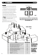
66..44 SSYYSSTTEEMM FFIILLLLIINNGG AANNDD PPRREESSSSUURRIISSIINNGG
1. A filling point connection on the central heating return
pipework must be provided for initial filling and pressurising
and subsequent topping up of the system.
A filling loop is provided loose with the boiler
2. The filling method adopted must comply with all relevant
water supply regulations and use approved equipment.
3. Further details are given in;
for GB: Guidance G24.2 and recommendation R24.2 of the
Water Regulations Guide.
f
or IE: the current edition of I.S. 813 “Domestic Gas
Installations”.
4. The sealed primary circuits may be filled or topped up using
a temporary connection between the circuit and a supply pipe,
provided a ‘Listed’ double check valve or some other no less
effective backflow prevention device is permanently connected
at the inlet to the circuit and the temporary connection is
removed after use.
1122
© Dimple
x Boiler
s 2008
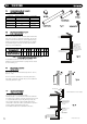
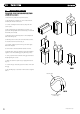
66..55 EEXXPPAANNSSIIOONN VVEESSSSEELL
1. The appliance expansion vessel is pre-charged to 1 bar.
Therefore the minimum cold fill pressure is 2 bar. The vessel is
suitable for correct operation for system capacities up to 84
litres. For greater system capacities an additional expansion
vessel must be fitted.
For GB refer to BS 7074 Pt 1.
For IE, the current edition of I.S. 813 “Domestic Gas
Installations”.
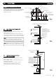
66..66 PPRREESSSSUURREE RREELLIIEEFF VVAALLVVEE
1. The pressure relief valve is set at 3 bar, therefore all
pipew
ork,
fit
tings, etc. should be suitable for pressures in
excess of 3 bar and temperature greater than 100°C.
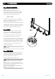
2. The pressure relief discharge pipe should be not less than
15mm diameter, run continuously downward, and discharge
outside the building, preferably over a drain. It should be
r
out
ed in such a manner
tha
t
no hazar
d occurs to occupants or
causes damage to wiring or electrical components. The end of
the pipe should terminate facing down and towards the wall.
NNOOTTEE:: BBooiilliinngg wwaatteerr//sstteeaamm ccoouulldd ddiisscchhaarrggee ffrroomm tthhee ppiippee,,
tthheerreeffoorree iitt sshhoouulldd bbee tteerrmmiinnaatteedd aawwaayy ffrroomm wwiinnddoowwss aanndd
ddoooorrss..
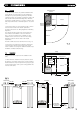
Mains
Supply
CH
Return
Pressure
Relief
Discharge
Pipe
Temporary
Loop
Stop
Valve
Stop
Valve
Double
Check
Valve
GasCH
Flow
Condensate
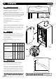
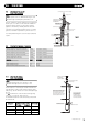
1
0 1 2 3 4 5 6 7 8 9 10 11 12 13 14 15 16 17 18
2
3
4
5
6
7
FLOW RATE Ltr/min
PUMP HEAD (mH
2
O)
System 18
System 30
AVAILABLE PUMP HEADS
FFiigg.. 88
FFiigg.. 77
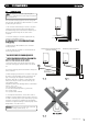
Expansion Vessel
P
ressure
R
elief V
alve
Vessel charge and initial
sy
s
t
em pressure
Total water content of
system using 8 litres
capacity expansion
vessel supplied with
appliance
For systems having a
larger capacity multiply
the t
otal system capacity
in litres by this factor to
obtain the total minimum
expansion vessel capacity
required in litres
bar
litres
0.5
96
0.75
84
0.093
1.0
73
1.5
50
FFiigg.. 66
FFiigg.. 99
FFiigg.. 1100
NNOOTTEE:: DDoo nnoott uussee tthhee pprreessssuurree rreelliieeff vvaallvvee ttoo ddrraaiinn tthhee ssyysstteemm,, bbeeccaauussee ddiirrtt
aanndd ddeebbrriiss ccoouulldd pprreevveenntt tthhee vvaallvvee sseeaattiinngg ccoorrrreeccttllyy..