
Technical data

99..00 IINNSSTTAALLLLAATTIIOONN
99..11 UUNNPPAACCKKIINNGG && IINNIITTIIAALL PPRREEPPAARRAATTIIOONN
TThhee ggaass ssuuppppllyy,, ggaass ttyyppee aanndd pprreessssuurree mmuusstt bbee cchheecckkeedd ffoorr
ssuuiittaabbiilliittyy bbeeffoorree ccoonnnneeccttiioonn
1. Remove the top cardboard tray from the carton.
2. The wall fixing jig is packed in its own cardboard sleeve.
Carefully slide this out of the carton.
3. To avoid scratching the boiler outercase, keep the outer
carton in place.
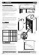
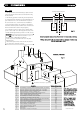
4. After reviewing the site requirements (see Section 7.0),
pos
ition the fixing template on the wall ensuring it is level both
horizontally and vertically.
5. Mark the position of the fixing holes for the wall plate and
boiler lower fixing holes.
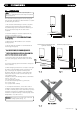
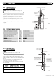
6. Mark the position of the centre of the flue hole (rear exit).
For side flue exit, mark as shown (Fig. 4).
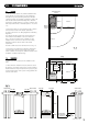
7. If r
equired, mark the position of the gas and water pipes.
Remove the template.
8. Cut the hole for the flue (minimum diameter 110mm).
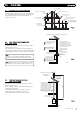
9. Drill the wall as previously marked to accept the wall plugs
supplied. Secure the wall fixing jig using the fixing screws.
10. Using a spirit level ensure that the fixing jig is level before
finally tightening the screws.
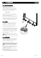
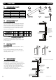
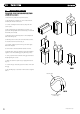
11. Flush and clean the system using an appropriate cleanser
(Fig. 30).
12. Connect the gas and water pipes to the valves on the wall
fixing jig.
13. Fit the filling loop as described in the instructions supplied
with it.
2200
© Dimple
x Boiler
s 2008
FFiigg.. 3300
Flushing Pipe
C
en
tral Heating Flow
or Return Pipe
FFiigg.. 2299