
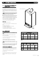
Technical data

99..00 IINNSSTTAALLLLAATTIIOONN
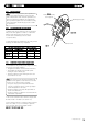
99..22 FFIITTTTIINNGG TTHHEE BBOOIILLEERR
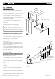
1. Remove the sealing caps from the boiler connections.
NOTE: A small amount of water may drain from the boiler
once the caps are removed.
2. Check the sealing washers are located correctly in the taps
on the wall jig.
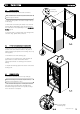
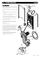
3. Lift the boiler as indicated by the shaded areas. The boiler
should be lifted by TWO PEOPLE. Engage the slots at the top
rear of the boiler on the wall plate (Fig. 31) (see
SSaaffee MMaannuuaall
HHaannddlliinngg
page 6).
4. Ensure the boiler is correctly located on the wall jig and the
connections align. Tighten all the connections.
© Dimple
x Boiler
s 2008
2211
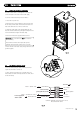
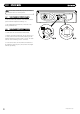
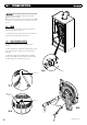
99..33 FFIITTTTIINNGG TTHHEE PPRREESSSSUURREE RREELLIIEEFF DDIISSCCHHAARRGGEE PPIIPPEE
1. Remove the two screws securing the front panel to the
underside of the boiler. Rotate the bottom of the panel out
slightly and lift the panel upwards off its retaining studs on top
of the appliance.
2. Determine the route of the discharge pipe.
3. Taking care not to disturb the case sealing grommet, the
pipework must be at least 15mm diameter and run
continuously downwards to a discharge point outside the
building.
4. Complete the discharge pipework and route it to the outside
discharge point.
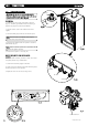
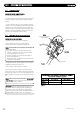
99..44 CCOONNDDEENNSSAATTEE DDRRAAIINN
1. Connect the condensate drain to the trap outlet pipe.
Ensure the discharge of condensate complies with any
national or local regulations in force.
2. The connection will accept 21.5 - 22mm plastic overflow
pipe which should g
ener
ally di
schar
ge internally into the
household drainage system. If this is not possible, discharge
into an outside drain is acceptable.
FFiigg.. 3333
Pressure Relief
Di
schar
g
e Pipe
Front Panel
Retaining Stud
XX 22
XX 22
FFiigg.. 3311
FFiigg.. 3322