
Technical data

1100..00 CCOOMMMMIISSSSIIOONNIINNGG
1100..11 CCOOMMMMIISSSSIIOONNIINNGG TTHHEE BBOOIILLEERR
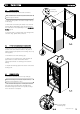
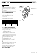
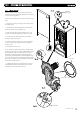
IIMMPPOORRTTAANNTT:: TThhee aaiirr vveenntt oonn ttoopp ooff tthhee bbooiilleerr mmuusstt bbee
OOPPEENN wwhheenn ffiilllliinngg tthhee ssyysstteemm.. AAttttaacchh aa ttuubbee ttoo tthhee aaiirr vveenntt
ttoo ssaaffeellyy ccoolllleecctt aannyy eexxcceessss wwaatteerr ((FFiigg.. 3388))..
GGaass TTiigghhttnneessss
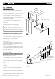
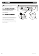
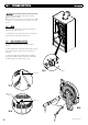
1. Ensure the gas service cock on the boiler is turned on
(Fig. 40). The entire gas installation must be tested for gas
tightness and purged in accordance with BS6891.
2. Open the service cocks to the CH flow and CH return
supplies.
3. C
onnect the filling loop and fill and vent the CH system.
NNOOTTEE::
Ensure the boiler is completely vented using the
manual air vent on top of the boiler.
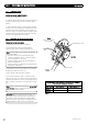
4. Drain, flush and refill the boiler and system in accordance
with BS7593 (Fig. 30).
NNOOTTEE::
Failure to flush the system and to add inhibitor will
in
validate the appliance warranty.
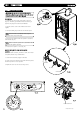
5. Pressurise the system to 1.5 bar (Fig. 42).
EElleeccttrriiccaall SSaaffeettyy CChheecckkss oonn tthhee CCoonnttrroollss SSyysstteemm
aanndd BBooiilleerr
6. Carry out earth continuity, resistance to earth, short circuit
and polarity checks using a suitable meter.
7. Switch on the electricity supply to the boiler.
8. Set the controls to call for heat. The boiler will now operate.
Check the system for correct operation.
9. Replace the outer door and two securing screws.
2244
© Dimple
x Boiler
s 2008
0
1
2
bar
3
4
Air Vent
Tube
FFiigg.. 3399
FFiigg.. 3388
FFiigg.. 4400
FFiigg.. 4411
FFiigg.. 4422
FFiigg.. 4433
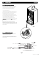
CH Return
CH Flow
Gas Inlet
Boiler Drain Point
0
1
2
bar
3
4