
Technical data

1122..00 SSEERRVVIICCIINNGG AANNDD MMAAIINNTTEENNAANNCCEE
1122..11 RROOUUTTIINNEE SSEERRVVIICCIINNGG AANNDD AALLLL MMAAIINNTTEENNAANNCCEE TTHHAATT
IINNVVOOLLVVEESS TTHHEE EEXXCCHHAANNGGEE OOFF PPAARRTT OOFF TTHHEE
CCOOMMBBUUSSTTIIOONN CCIIRRCCUUIITT
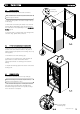
1. During routine servicing, e.g. an annual service check, and
after all maintenance that involves the exchange of parts of
the combustion circuit, we recommend that (in this order) the
integrity of the full flue system and combustion circuit seals,
the inlet gas pressure, gas rate and combustion performance is
verified.
NNOOTTEE::
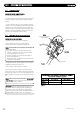
The combustion circuit on this appliance comprises
of the PCB, fan, air/gas ratio valve, burner, burner door,
combustion box door, injector and flue system.
2. T
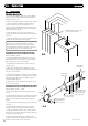
o ensure continued safe and efficient operation of the
appliance it is recommended that the boiler is serviced at least
annually. Servicing must be performed by a competent person.
BS 7967-1 gives guidance on identifying and managing
sources of fumes, smells, spillage/leakage of combustion
products and carbon monoxide detector activation.
SSaaffeettyy CChheecckkss
On any service visit always check;
a. Condition of flue system, both air and combustion products
ducts.
b. Condition of seals and joints.
c. For evidence of leakage of combustion products.
d. For evidence of heat staining.
e. For operation at maximum heat input.
f. The general condition of the boiler and its components.
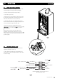
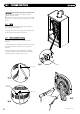
11.. CCoommbbuussttiioonn cchheecckkss mmuusstt bbee ccaarrrriieedd oouutt wwiitthh tthhee oouutteerrccaassee
ffiitttteedd..
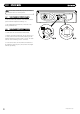
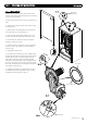
2. Remove the sampling cap from the boiler flue elbow or
boiler vertical flue adaptor.
3. Insert the pr
obe
f
r
om the port
able electronic combustion
analyser into the sampling point.
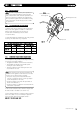
4. W
ith the appliance operational, connect the flue gas
analyser to the flue sampling point as shown in Fig. 47.
NNOOTTEE::
The out
er
case mus
t
be
fit
t
ed
f
or all combustion
checks.
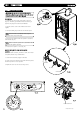
5. W
ith the boiler
a
t
minimum r
ate and then at maximum rate
(allowing the combustion to stabilise at each rate before taking
a reading) carry out the combustion checks as follows:
CCOOMMBBUUSSTTIIOONN CCHHEECCKKSS AATT MMIINNIIMMUUMM RRAATTEE
6. The combus
tion v
alues at minimum gas rate and maximum
g
as r
a
t
e mus
t
be checked us
ing a suit
able calibrated flue gas
analyser. Further guidance is detailed in BS7967 parts 1 to 4.
7. Se
t
the boiler
in
to Service Mode at Min Rate
(see section 11.1).
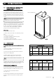
8. Check the Carbon Monoxide (CO) and Carbon Dioxide (CO
2
)
readings are within the range quoted in the tables opposite
(T
able 1).
© Dimple
x Boiler
s 2008
2277
1122..22 CCOOMMBBUUSSTTIIOONN CCHHEECCKKSS
0
1
2
b
a
r
3
4
FFiigg.. 4477
Flue Gas Sampling Point
M
M
i
i
n
n
i
i
m
m
u
u
m
m
G
G
a
a
s
s
R
R
a
a
t
t
e
e
N
N
G
G
Boiler
Model
(kW)
1188
3300
Carbon
Monoxide
CO
p.p.m
0 - 40
0 - 40
Carbon
Dioxide
C
O
2
%
8.5 - 8.9
8.7 - 9.1
L
L
P
P
G
G
Carbon
Monoxide
CO
p.p.m
80 - 160
80 - 160
Carbon
Dioxide
C
O
2
%
10.4 - 10.8
10.3 - 10.7
M
M
a
a
x
x
i
i
m
m
u
u
m
m
G
G
a
a
s
s
R
R
a
a
t
t
e
e
N
N
G
G
Boiler
Model
(kW)
1188
3300
C
arbon
Monoxide
C
O
p.p.m
15 - 60
15 - 60
C
arbon
Dioxide
CO
2
%
8.8 - 9.2
8.8 - 9.2
L
L
P
P
G
G
C
arbon
Monoxide
C
O
p.p.m
80 - 160
80 - 160
C
arbon
Dioxide
CO
2
%
10.8 - 11.2
10.5 - 10.9
TTaabbllee 11
TTaabbllee 22