
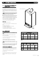
Technical data

1122..00 SSEERRVVIICCIINNGG AANNDD MMAAIINNTTEENNAANNCCEE
1122..11 AANNNNUUAALL SSEERRVVIICCIINNGG
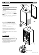
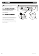
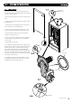
8. Remove the two screws securing the front panel to the
underside of the boiler. Lift the panel upwards off its retaining
studs on top of the appliance.
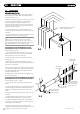
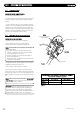
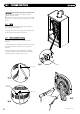
9. Disconnect the two leads to the fan and one lead to the gas
valve.
10. Undo the nut on the gas inlet pipe to the valve and retain
the sealing washer.
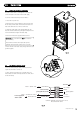
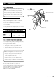
11. Remove the four nuts holding the burner door plate and
remove the valve and fan assembly (Fig. 51).
12. Clean any debris from the heat exchanger using a soft
brush and check that the gaps between the tubes are clear.
13. Inspect the burner, electrode positions and insulation,
cleaning or replacing if necessary.
14. Check the condition of the burner door seals, replacing if
necessary. Check for gas tightness and check combustion
cir
cuit is sealed.
15. Reassemble in reverse order.
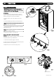
16. To check if the condensate pipe is clear, carefully remove
the pipe from the bottom of the primary heat exchanger. Blow
down the pipe to ensure it is clear. If required loosen any
debris with a small conical brush and flush through with
water. Before reassembly, fill the condensate pipe with water
to ensure a water trap is formed. Finally, ensure the grommet
fitted to the condensate pipe is correctly located into the hole
in the bottom of the boiler case.
17. Complete the relevant Service Interval Record section of
the Benchmark Commissioning Checklist at the rear of this
publication and then hand it back to the user.
© Dimple
x Boiler
s 2008
2299
FFiigg.. 5511
FFiigg.. 4499
FFiigg.. 5500
FFiigg.. 5522
Gas Inlet Nut
Front Panel
Retaining Stud
XX 44
XX 22
XX 22
Burner Door Seal
Inner Seal