
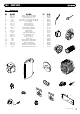
Technical data

1133..00 CCHHAANNGGIINNGG CCOOMMPPOONNEENNTTSS
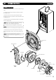
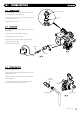
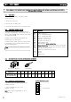
1133..33 GGAASS VVAALLVVEE AANNDD FFAANN
1. Disconnect the two leads to the fan and one lead to the gas
valve.
2. Undo the nut on the gas inlet pipe to the valve and retain
the sealing washer.
3. Remove the three securing screws holding the air/gas
Channel to the burner door plate and remove the valve and fan
assembly (Fig. 57).
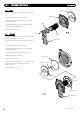
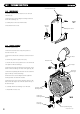
4. Remove the three screws holding the valve and swirl plate
to the fan adaptor plate.
NNOOTTEE::
Mark on the adaptor plate which holes are being
used by the screws. Using the wrong holes on
re-assembly will cause mis-alignment of the gas valve.
FFaann OOnnllyy
6. Remove the three screws holding the fan adaptor to the fan.
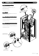
7. Remove the four screws securing the fan to the air/gas
channel. R
eassemble in reverse order ensuring all seals are in
place.
NNOOTTEE::
The gas valve throttle should be adjusted in
accordance with the instructions supplied in the spares kit
See Section 10.
© Dimple
x Boiler
s 2008
3311
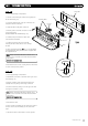
FFiigg.. 5577
Swirl Plate
F
an
Fan Gasket
Burner Door
Air/Gas Channel
Fan Adaptor Plate
Injector Plate
Inject
or
Injector ‘O’ Ring
Gas Valve