
Technical data

1133..00 CCHHAANNGGIINNGG CCOOMMPPOONNEENNTTSS
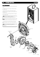
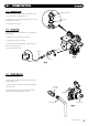
1133..44 BBUURRNNEERR
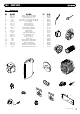
1. Remove the valve and fan assembly as described in Section
13.3.
2. Examine the gasket and replace if necessary.
3. Undo the four nuts securing the burner door and remove
from the heat exchanger.
4. Slowly withdraw the burner from the burner plate taking
care not to damage the insulation (Fig. 58).
5. Reassemble in reverse order.
3322
© Dimple
x Boiler
s 2008
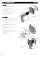
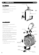
1133..55 IINNSSUULLAATTIIOONN
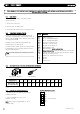
1. Remove the electrode leads, noting their positions. Remove
the electrodes as described in section 13.2.
2. R
emove the valve and fan assembly as described in Section
13.3.
3. Examine the gasket and replace if necessary.
4. Undo the four nuts securing the burner door and remove
from the heat exchanger.
5. Slowly withdraw the burner from the burner door.
6. Replace the insulation if necessary.
7. Check the burner door seals.
8. The rear insulation is retained by a screw and large washer,
remove these and draw the insulation out of the heat
exchanger (Fig. 59).
9. Reassemble in reverse order.
Burner
Insulation
Gasket
Air/Gas Channel
Rear Insulation
Washer
Insulation
Retaining Screw
Burner Assembly
Burner Door
Burner Door Seal
FFiigg.. 5588
FFiigg.. 5599
Inner Seal