
Technical data

1133..00 CCHHAANNGGIINNGG CCOOMMPPOONNEENNTTSS
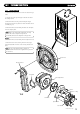
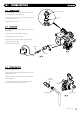
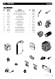
1133..1100 PPUUMMPP -- HHEEAADD OONNLLYY
1. Drain the primary circuit and disconnect the wiring
connector from the pump head.
2. Remove the four socket head screws securing the pump
head to the body and draw the head away (Fig. 62).
3. A replacement Grundfos 15-60 head can now be fitted
(Fig. 62)(Part No: 500672).
4. Reassemble in reverse order.
5. Replace the wiring connector into the socket on the pump
he
ad.
3344
© Dimple
x Boiler
s 2008
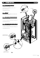
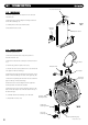
1133..1111 HHYYDDRROOBBLLOOCCKK
1. Dr
ain the primary circuit.
2. Remove the stainless clip at the base of the hydro-block and
di
sconnect the pipe (Fig. 63).
3. Un-lock the locking clip on the return port.
4. Disconnect the discharge pipe from the pressure relief valve.
5. Remove the two securing screws from below the boiler.
6. Carefully remove the hydro-block and change the relevant
components.
7. Reassemble in reverse order taking care to replace all the
clips correctly. Ensure the locking clip is in the ‘Locked’
position as shown opposite.
Pump Head
F
r
on
t
Stainless Clip
R
ear
Stainless Clip
Un-Locked
(v
iewed from pipe end)
Locked
(v
iewed from pipe end)
XX 22
FFiigg.. 6622
FFiigg.. 6633