
Technical data
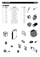

1133..00 CCHHAANNGGIINNGG CCOOMMPPOONNEENNTTSS
3366
© Dimple
x Boiler
s 2008
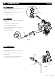
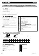
1133..1166 EEXXPPAANNSSIIOONN VVEESSSSEELL
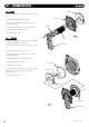
1. Drain the primary circuit and undo the nut on the vessel
connection pipe.
2. Remove the two screws holding the retaining bracket and
remove the bracket (Fig. 67).
3. Carefully slide out the vessel from the boiler.
4. Reassemble in reverse order.
Expansion Vessel
Vessel Connection Pipe
Retaining
Bracket
FFiigg.. 6677
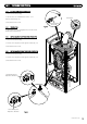
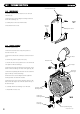
FFiigg.. 6688
Flue Elbow
Flue Adaptor
Main He
a
t
Exchanger
Left
Hand
R
e
t
aining Br
acke
t
Right Hand
Retaining Bracket
Flow Pipe
R
e
t
aining Clip
Return Pipe Retaining Clip
Manual Air Vent
1133..1177 MMAAIINN HHEEAATT EEXXCCHHAANNGGEERR
1. Drain the primary circuit.
2. Remove the electrode leads, noting their positions as
described in section 13.2.
3. Remove the valve and fan assembly as described in Section
13.3.
4. Examine the gasket and replace if necessary.
5. Undo the four nuts securing the burner door and remove the
cover plate from the heat exchanger.
6. R
emo
v
e the tw
o clips
from the flow and return pipes on the
bottom of the heat exchanger and slide out the pipes (Fig. 68).
7. Remove the clip holding the manual air vent and remove the
pipe
f
r
om the t
op of the heat exchanger.
8. Remove the four screws holding the left and right hand
retaining brackets and remove the brackets.
9. R
emove the four screws securing the flue to the top of the
boiler. Lift the flue adaptor out of the flue outlet in the top of
the heat exchanger.
10. C
ar
efully slide the he
at exchanger out of the boiler.
11. Reassemble in reverse order.