
Technical data

1133..00 CCHHAANNGGIINNGG CCOOMMPPOONNEENNTTSS
1133..1188 PPCCBB
1. Ensure supply voltage is fully isolated.
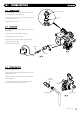
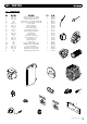
2. Undo the screws holding the control box and gently ease
the box forward (Fig. 69).
3. Locate the retaining barbs on the top of the fascia and
unclip them from the control box.
4. Unclip the PCB from the plastic control box.
5. Note the positions of all the connections on the PCB
and disconnect them.
(DO NO
T REMOVE THE YELLOW BCC (Fig. 69))
6. Carefully unclip and remove the ribbon cable
from the PCB and withdraw.
7. Fit all the connection plugs to the new PCB
including the ribbon cable, take care not to damage
the PCB.
8. U
nless specifically instructed
NNOOTT
t
o do so by the Dimplex
Service Department, always fit the new BCC if supplied with
the replacement PCB.
NNOOTTEE::
Always double check the label on the BCC card to
ensure it is the correct BCC for the boiler model to which it
is being fitted.
NNEEVVEERR FFIITT AANN IINNCCOORRRREECCTT BBCCCC..
9. Reassemble in reverse order, ensuring that the control knob
are reset to their previous positions
© Dimple
x Boiler
s 2008
3377
1133..1199 BBCCCC
1. Ensure supply voltage is fully isolated.
2. Di
sman
tle the con
t
rol box as described above to gain access
t
o the PCB (Fig. 69).
3. Note the orientation of the existing BCC (if fitted) and
carefully remove by sliding it off the edge of the PCB.
4. Re-fit the new BCC by sliding it onto the edge of the PCB,
ensuring the orientation is correct.
NNOOTTEE::
Alway
s double check the l
abel on the B
CC card to
ensure it is the correct BCC for the boiler model to which it
is being fitted.
NNEEVVEERR FFIITT AANN IINNCCOORRRREECCTT BBCCCC..
5. Reassemble as above.
6. Power up boiler, and briefly press the reset button, wait for
a
t
least 5 seconds and then briefly press the reset button
ag
ain.
7. The boiler should now be checked for correct operation.
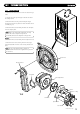
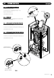
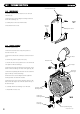
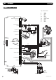
P
CB
Facia
Control Box
Retaining Barbs
Pressure
Gauge
User Interface
Control Knob
FFiigg.. 6699
BCC