
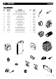
Technical data
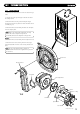

1166..00 FFAAUULLTT FFIINNDDIINNGG
4400
© Dimple
x Boiler
s 2008
1. The mains electrical supply to the boiler and system
controls are turned on.
2. The gas service cock is open.
3. External controls are calling for heat.
4. The system is filled with water and is correctly pressurized.
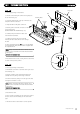
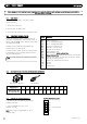
To follow the operational sequence of the boiler, press the
reset button for approximately 3 seconds until the two dots on
the LCD display are flashing. With no demand for Heat or DHW,
the di
splay will show
00.
On Demand for heat or DHW, the display will show the
con
troller sequence. See table opposite.
To reset the display to normal operation, press the reset button
for approximately 1 second. The display will revert to show
the current boiler temperature.
NNOOTTEE::
To reset the appliance after a lockout, press the Red
button.
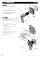
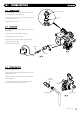
1166..11 BBAASSIICC CCHHEECCKKSS
1166..44 CCHHEECCKKIINNGG GGAASS VVAALLVVEE SSOOLLEENNOOIIDD CCOOIILLSS
1166..22 OOPPEERRAATTIIOONNAALL SSEEQQUUEENNCCEE OOFF BBOOIILLEERR
1166..33 RREESSIISSTTAANNCCEE VVAALLUUEESS ΩΩ FFOORR FFLLOOWW,, RREETTUURRNN AANNDD FFLLUUEE TTHHEERRMMIISSTTOORRSS
DDiissppllaayy
00
01
02
03
04
05
06
07
08
09
10
11
12
13
14
EExxppllaannaattiioonn
Standby - Burner off
Fan on - Checking RPM feedback
F
an on - Checking RPM feedback
Pre purge of combustion circuit
Pre-ignition - gas valve closed
Gas valve open and ignition on
Flame stabilisation check
Flame established -
BBuurrnneerr oonn ppeerriioodd ssttaarrttss
BBuurrnneerr ooffff ppeerriioodd ssttaarrttss..
Check gas valve solenoids are de-energised
Check gas valve solenoids are de-energised and check for no flame
Post purge of combustion circuit
Volatile or non-volatile lockout has occurred
Not used
Not used
Sequence fault
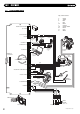
BBeeffoorree cchheecckkiinngg ffoorr aa ffaauulltt ccoonnddiittiioonn ccaarrrryy oouutt eelleeccttrriiccaall cchheecckkss ttoo eennssuurree tthhee bbooiilleerr hhaass EEaarrtthh ccoonnttiinnuuiittyy,, ccoorrrreecctt ppoollaarriittyy aanndd LLiivvee aanndd NNeeuuttrraall
ccoonnnneeccttiioonnss hhaavvee nnoo sshhoorrtt cciirrccuuiitt..
TTeemmppeerraattuurree °°CC
5
RReessiissttaannccee OOhhmmss ((ΩΩ))
12890 7856 6245 5000 3265 2185 1242 625 456 390 337
NNOOTTEE::
Allow a tolerance of approximately +/- 10%.
15 20 25 35 45 60 80 90 95 100
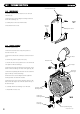
1. The solenoid coils can be checked by measuring the
resistance in Ohms (Ω).
2. C
onnect a multimeter across pins 1 and 5,
resistance = 3770 Ω.
NNOOTTEE::
Allow a tolerance of approximately +/- 10% on
r
es
i
s
t
anc
e r
e
ading.
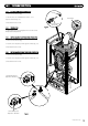
Pin 1
Pin 2
Pin 3 - Earth C
onnection
GGaass VVaallvvee EElleeccttrriiccaall CCoonnnneeccttiioonnss
Pin 4
Pin 5
Flow and R
eturn Thermistors
Flue Thermistor