
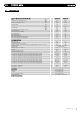
Technical data

11..00 IINNTTRROODDUUCCTTIIOONN
1. The appliances incorporate a microprocessor based, fully
modul
a
ting air/g
as r
atio control system with direct burner
ignition. This provides a modulated heat output, with internal
frost protection provided as standard. The heat exchanger is
cons
t
ruct
ed from stainless steel encased in high temperature
polymer.
A combined circulating pump, automatic air vent assembly,
pressure gauge, safety valve and system expansion vessel are
included.
Isolation valves are fitted to the service connections.
The boiler
has a pump o
ver run feature therefore the central
heating system must include either a proprietary automatic
bypass valve or a radiator must be fitted with lock shield
valves. A separate CH expansion vessel is not required if the
total CH system content is less than 84 litres. However one is
required for systems with volumes greater than 84 litres; refer
t
o section 6.5. It
i
s r
ecommended tha
t
a drain cock is fitted at
the lowest point in the system.
66
© Dimple
x Boiler
s 2008
11..55 DDEESSCCRRIIPPTTIIOONN
RF room thermostats etc, are available as optional extras,
howe
v
er
if an e
xternal control is fitted the hole in the fascia
must be covered using the fascia blanking panel supplied (Part
No. 300635)
2. The boiler is designed for use on Natural Gas (G20). A
natural gas to propane conversion kit is available for each
Dimplex System Boiler.
3. The boiler is suitable for use only on fully pumped sealed
heating systems.
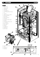
4. The boiler data badge gives details of the model, serial
number and Gas Council number and is situated on the inner
door panel. It is visible when the case front is removed. (Fig. 1)
5. The boiler model name and serial number are also shown on
the information label on the inside of the fascia. This is for
user reference.
6. The boiler is intended to be installed in residential /
commercial / light industrial E.M.C. environments on a
governed meter supply only.
7. The boiler must be installed with one of the purpose
designed flues such as the standard horizontal telescopic flue
kit, part no. 956120.
8.
AAllll ssyysstteemmss mmuusstt bbee tthhoorroouugghhllyy fflluusshheedd aanndd ttrreeaatteedd wwiitthh
iinnhhiibbiittoorr ((sseeee sseeccttiioonn 66..22))..
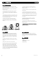
11..66 OOPPTTIIOONNAALL EEXXTTRRAASS
• Boiler
• Wall fixing jig
• T
emplates & ‘Quick Fit’ Guide
• Literature Pack
• Plugs and screws
11..77 PPAACCKK CCOONNTTEENNTTSS
11..44 SSAAFFEE MMAANNUUAALL HHAANNDDLLIINNGG
1. The boiler should be handled and lifted by two people.
Wear appropriate Personal Protection Equipment e.g. protective
gloves, safety footwear etc.
Plan your route to minimise the number of turns needed to
handle/lift the boiler.
2. Where possible transport the boiler using a sack truck or
other suitable trolley. Try to avoid steps, wet or slippery
surfaces, unlit areas etc. and take special care on ladders/into
lofts.
3. When handling or lifting always use safe techniques - keep
your back straight, bend your knees. Don’t twist - move your
feet, avoid bending forwards and sideways and keep the load
as close to your body as possible.
4. Asses the risks associated with handling and lifting
according to the conditions on site. If in doubt seek advice
before proceeding. Health and Safety is the responsibility of
everyone.