
VF2927L, VF5452L Opti V Service Manual
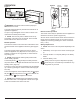
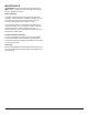
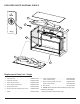

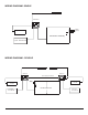
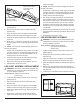
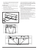
Table Of Contents

10 www.dimplex.com
Figure 7
Securing Screws
Securing Screws
tom of the unit (2 on either end) and remove the logset.
For the double units remove both logsets, taking note
of the left and right.
!
NOTE: The screws are recessed slightly into the em-
ber bed of the logset.
7. Disconnect the logset LED’s from the LED controller
board and set in a safe place.
8. Remove the power supply wireharness that runs from
one LED controller board to the other.
9. On the top front surface of the rebox there are a sec-
Figure 6
ond set of logs that reect on to the glass. Locate the
nuts that secure the logset to the rebox - single units,
there is one on either end, double units there are three,
two on each end and one in the middle.
!
NOTE: The nuts are recessed slightly into the ember
bed of the logset.
10. Using a 5/16” (M8) socket wrench remove the nuts to
remove the logset. There is a slight ledge at the top of
the front opening that will help hold the logset from fall-
ing while the screws are being removed.
11. Remove the two screws securing the center bracket to
the unit (double unit only) (Figure 6).
12. Remove the top panel of the unit by removing the 3
screws along the top back portion of the unit, start with
the outter two then remove the center one last.
13. Slide the top panel towards the back the let the front
drop down and pull out the front opening.
14. Locate the securing screws of the LED Screen (Figure
7) and remove the LED Screen.
15. Reassemble in the reverse order.