
VF2927L, VF5452L Opti V Service Manual
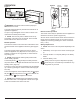
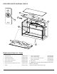

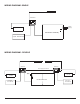
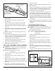
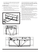
Table Of Contents

8 www.dimplex.com
FRONT GLASS REPLACEMENT
WARNING: Disconnect power before attempting any
maintenance or cleaning to reduce the risk of electric
shock or damage to persons.
Tools required: Phillips head screwdriver
Suction Cups
1. Locate the glass retention strip at the top of the front
glass (Figure 3).
2. Remove the securing screws on either side of the
retention strip.
3. Apply the suction cups to the glass at a comfortable
distance to allow for easily removing the front glass.
4. Gently tilt the glass forward, lift up and lift the glass out
of the unit.
5. Reassembly in the revers order.
BOTTOM LOGSET REPLACEMENT
WARNING: Disconnect power before attempting any
maintenance or cleaning to reduce the risk of electric
shock or damage to persons.
Tools required: Phillips head screwdriver
Suction Cups
1. Locate the glass retention strip at the top of the front
glass (Figure 3).
2. Remove the securing screws on either side of the
retention strip.
3. Apply the suction cups to the glass at a comfortable
distance to allow for easily removing the front glass.
4. Gently tilt the glass forward, lift up and lift the glass out
of the unit.
5. Locate the 4 screws that secure the logset to the bot-
tom of the unit (Figure 4) and remove the logset(s).
!
NOTE: The screws are recessed slightly into the em-
ber bed of the logset.
6. Disconnect the logset LED’s from the LED controller
board.
7. Replace connection with new logset LED wire.
8. Reassembe in the revers order.
TOP LOGSET REPLACEMENT
WARNING: Disconnect power before attempting any
maintenance or cleaning to reduce the risk of electric
shock or damage to persons.
Tools required: Phillips head screwdriver
5/16” (8 mm) socket wrench
Suction Cups
1. Locate the glass retention strip at the top of the front
glass (Figure 3).
2. Remove the securing screws on either side of the
retention strip.
3. Apply the suction cups to the glass at a comfortable
distance to allow for easily removing the front glass.
4. Gently tilt the glass forward, lift up and lift the glass out
of the unit.
5. Remove the bottom logset (only the corresponding log-
set to the side that needs to be repaired on the double
unit). Locate the 4 screws that secure the logset to the
bottom of the unit (Figure 4) and remove the logset.
!
NOTE: The screws are recessed slightly into the em-
ber bed of the logset.
6. On the top front surface of the rebox there are a sec-
ond set of logs that reect on to the glass. Locate the
nuts that secure the logset to the rebox - single units,
there is one on either end, double units there are three,
two on each end and one in the middle.
!
NOTE: The nuts are recessed slightly into the ember
bed of the logset.
7. Using a 5/16” (M8) socket wrench remove the nuts to
remove the logset. There is a slight ledge at the top of
the front opening that will help hold the logset from fall-
ing while the screws are being removed.
8. The wiring for the logset is connected to the LED con-
troller located on the botton panel of the rebox below
the bottom logset. Disconnect the LED connector for
the top logset from the LED controller and attach a
peice of string to the end that can be led through the
corner to pull the new LED connector back through.
9. Replace the top logset.
10. Reassemble in the reverse order.
LED CONTROLLER REPLACEMENT
WARNING: Disconnect power before attempting any
maintenance or cleaning to reduce the risk of electric
shock or damage to persons.
Tools required: Phillips head screwdriver
Suction Cups
Figure 3
Securing Screws