
Operating instructions


If there is no existing chimney then either a prefabricated block
chimney or a twin walled insulated stainless steel ue to BS4543
can be used. These chimneys must be tted in accordance with
the manufacturers instructions and in compliance with Building
Regulations.
This product must not be installed on a shared ue.
Flue Deposits
If the chimney was previously used as an open re, it is possible
that the higher ue gas temperatures generated by the stove
may loosen deposits that were previously adhered to the inner
surface of the ue pipe which could cause blockage of the ue
pipe. We recommend that in this situation a second sweeping of
the chimney should be carried out within one month of initial stove
use after installation.
Flue Draught
The chimney should be checked before the stove is installed to
ensure that there is adequate ue pull. The draught can be checked
initially by using a smoke match close to the ue opening. If the
chimney doesn’t pull the smoke it may suggest that the chimney
needs further attention. Any remedial work to the chimney ue
should be carried out by a suitably Qualied Engineer.
A ue draught of minimum 12 Pascal to maximum 25 Pascal is
required for satisfactory appliance performance. The ue draught
should be checked under re at high output and if it exceeds the
recommended maximum a ue draught stabiliser (or ue damper
as it is also known) must be tted so the rate of burning can be
controlled and prevent overring.
Room Ventilation
For safe operation this stove must be provided with combustion
air supply in addition to normal room ventilation, in accordance
with Building Regulations. Minimum ventilation requirements vary
depending on whether the dwelling is considered to be of standard
construction or of airtight construction, or if a ue draught stabiliser
has been tted. The required open air vent sizes are as follows:
Table 4 - Additional Room Ventilation Required
Standard build dwellings {air
permeability >5.0m³ /(h.m²)}
Westcott 5 Westcott 8
No Flue Stabiliser Not Required 17 cm²
With Flue Stabiliser 15 cm² 41 cm²
Airtight build dwellings {air
permeability ≤5.0m³ /(h.m²)}
Westcott 5 Westcott 8
No Flue Stabiliser 28 cm² 44 cm²
With Flue Stabiliser 43 cm² 68 cm²
An extractor fan must not be used in the same room as this
appliance.
Floor Protection & Installation Clearances
In all instances the stove should be positioned on a non-
combustible hearth. The construction of the hearth must conform
to Building Regulations, must be rm, non-combustible and capable
of supporting the stove. Care should be taken to ensure the stove
is level and the hearth is secure. The hearth itself should not be
less than 125mm thick, including the thickness of the oor and
any decorative top surface (e.g. tiling). Allow an apron of at least
300mm at the front of the stove in case of spills when de-ashing.
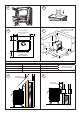
(Fig 6) shows the minimum distances required from the hearth
edge to the sides of the stove.
- 2 -
The stove can also be recessed in a suitable sized replace. We
recommend a permanent free air gap of at least 150mm should
be left around the sides where possible and 300mm around the
top to obtain maximum heat output and for access to the rear of
the stove. Place the product in the desired location on reproof
hearth taking note of installation clearances from adjacent walls
(Fig 7). Adjust the screws on the bottom of the feet to ensure the
stove is level and steady (see ‘A’ Fig 2). The stove can be screw
xed to the oor when placed in the desired position, using the
holes provided in the feet.
Table 5 shows the minimum safe distances to combustable
materials that must be observed. Any surrounding combustible
material should not exceed 80°C.
Table 5 Sides Rear
Westcott 5kW 600mm 400mm
Westcott 8kW 600mm 480mm
Flue Pipes
The ue pipe used to connect to the stove should be made of
cast iron, 316 grade stainless steel or vitreous enamelled steel,
nominal thickness 1.2mm. The diameter of the ue pipe should
be 125mm (5”) for the Westcott 5kW and 150mm (6”) for the
Westcott 8kW models.
Connect the ue pipe to the stove making sure that it ts snugly
into the base of the ue collar (Fig 5). Seal the collar and ue
connection with re cement or with other suitable high temperature
sealant. Add ue sections as required; note that all ue sockets
must face upwards. Ensure that the ue pipe end is no closer
than 76mm to the side or rear of the chimney walls. It is essential
that all connections between the stove and the chimney ue are
sealed and made airtight.
Avoid using bends greater than 45° to the vertical (Fig 8). All ue
pipes should be as close to vertical where possible. For rear ue
connection the length of the horizontal run of the ue pipe should
not exceed 150mm (Fig 9). Both chimney and ue pipe must be
accessible for cleaning and if ALL parts of the chimney cannot be
reached, a soot door must be tted to enable this to be done.
Existing Fireplace
An existing replace opening can be bricked up or sealed with a
register plate, 2.5mm sheet steel or concrete. A short length of
ue pipe may then be used to connect the stove to the chimney.
Ideally the old replace should be lled in so that there is a smooth
streamlined entry into the ueway. (Fig 9)
Typical installation for Inglenook Fireplaces
Inglenook replaces can have very large bore chimneys (Fig 10).
Check with your installer – you may need a stainless steel exible
ue liner for solid fuel tting.
Flue Damper (Not Supplied)
When burning wood, a ue damper may be tted to reduce the
draught through the stove if the draught is too high. When the
damper is set in the open position the chimney draws at full
draught, increasing the volume of air ow through the stove and
ue. Shutting the damper restricts the ow, slowing the rate of
burning. The damper should be tted to the stove ue and should
be the same size as the ue pipe. As a rule it should be tted no
closer than 700mm from the ue outlet of the appliance.
A ue damper should not be tted when burning solid fuels
other than wood.