Service Manual Model XHD23L/XHD23G XHD26L/XHD26G XHD28L/XHD28G Part Number 6909940XXX 6909850XXX 6909970XXX IMPORTANT SAFETY INFORMATION: Always read this manual first before attempting to service this firebox. For your safety, always comply with all warnings and safety instructions contained in this manual to prevent personal injury or property damage.
Table of Contents Operation. . . . . . . . . . . . . . . . . . . . . . . . . . . . . . . . . . . . . . . . . . . . . . . . . . . . . . . . . . . 3 Exploded Parts Diagram. . . . . . . . . . . . . . . . . . . . . . . . . . . . . . . . . . . . . . . . . . . . . . . 6 Replacement Parts List. . . . . . . . . . . . . . . . . . . . . . . . . . . . . . . . . . . . . . . . .
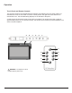
Operation Touch Panel and Remote Controls The manual controls for the Dimplex Electric Fireplace are located on the front panel. When not activated, the icons are not visible. Touch the control panel to the right side of the white line to activate the icons. The selected setting displays on the left side of the panel. A multi-function IR (infrared) remote control also is provided. The remote control has a range of approximately 30 ft (9 m).
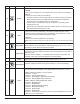
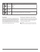
Icon A Function Power B Heat Description Press to turn unit Off or On. • Unit Off Press to turn everything Off. Press again to turn unit On with previous settings. • Unit On Press to turn unit On with previous settings. --If the flame effect was On, the flame will turn on and the previous heat setting will be activated (On or Off). Display will show current heater temperature setting and after 2 sec displays the room temperature.
Icon F Function Brightness Description Press to change the flame and logs brightness. Display will show b3, b1, b2 respectively. • High • Low • Medium Press to turn the flame effect On. Press again to turn the flame effect Off. G H Demo Mode Flame Timer Press multiple times to change the sleep timer by 0.5 hr from 0.5 hr to 8 hr before turning off. Press again, the remaining time on the timer displays.
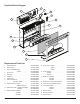
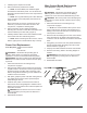
Exploded Parts Diagram 3 2 4 19 18 1 5 6 7 8 9 10 12 13 17 Replacement Parts List 1. Heater Assembly . . . . . . . . . . . . . . . . . . . . . . 2203730300RP 12. Flame Screen XHD23 . . . . . . . . . . . . . . . . . . 5902580400RP 2. Power Supply . . . . . . . . . . . . . . . . . . . . . . . . . 2100250700RP XHD26 . . . . . . . . . . . . . . . . . . 5902580500RP 3. Main Control Board Logs. . . . . . . . . . . . . . . . 3001840100RP XHD28 . . . . . . . . . . . . . . . . . .
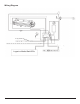
Wiring Diagram On log models only Logset or Media Bed LEDs 7
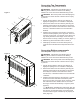
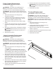
Accessing Top Components Tools Required: Phillips head screwdriver Figure 1 WARNING: If the firebox was operating prior to servicing, allow at least 10 minutes for the heating elements to cool off to avoid accidental burning of skin. WARNING: Disconnect power before attempting any maintenance to reduce the risk of electric shock or injury to persons. 1. Unhook the front glass to remove it by pulling it up slightly and pulling it out. Set it aside in a safe place. 2.
4. Carefully lay the fireplace on its back. 5. Remove the bottom panel and set it aside. ! NOTE: On the XHD28G, the media bed lights are attached to this bottom panel. You can disconnect these lights to have better access to the components in the firebox. ! NOTE: The log set/media tray has a wire attached to the unit which can be temporarily disconnected for easier access. Most components can now be accessed for service.
Power Supply Replacement Tools Required: Phillips head screwdriver Pliers WARNING: If the firebox was operating prior to servicing, allow at least 10 minutes for the heating elements to cool off to avoid accidental burning of skin. WARNING: Disconnect power before attempting any maintenance to reduce the risk of electric shock or injury to persons. 1. Follow the instructions for accessing the top components on page 8. 2.
Flicker Motor Replacement Tools Required: Phillips head screwdriver Pliers Side cutters WARNING: If the firebox was operating prior to servicing, allow at least 10 minutes for the heating elements to cool off to avoid accidental burning of skin. WARNING: Disconnect power before attempting any maintenance to reduce the risk of electric shock or injury to persons. 1. Follow the instructions for accessing the bottom components on pages 8-9. 2.
Flame LED Strip Replacement Tools Required: Phillips head screwdriver WARNING: If the firebox was operating prior to servicing, allow at least 10 minutes for the heating elements to cool off to avoid accidental burning of skin. WARNING: Disconnect power before attempting any maintenance to reduce the risk of electric shock or injury to persons. 1. Follow the instructions for accessing the bottom components on pages 8-9. 2. Locate the plastic LED holder bar and remove the screw on either side (2 total).
Thermistor Replacement Flame Screen Replacement Tools Required: Phillips head screwdriver Side cutters Tools Required: Phillips head screwdriver WARNING: If the firebox was operating prior to servicing, allow at least 10 minutes for the heating elements to cool off to avoid accidental burning of skin. WARNING: Disconnect power before attempting any maintenance to reduce the risk of electric shock or injury to persons.
Troubleshooting Guide PROBLEM CAUSE SOLUTION General Circuit breaker trips or fuse blows when unit is turned on Power cord gets warm Firebox does not turn on using the manual controls Firebox does not respond to the remote control Improper circuit current rating Additional appliances may exceed the current rating of the circuit breaker or fuse. Plug unit into another outlet or install unit on a dedicated 15 amp circuit.
Heater Heater is not turning on Heater cuts out after a short time Set temperature is below room temperature See operation instructions Heat is disabled; --- is displayed when heat button is pressed See operation instructions Defective heater assembly Replace heater assembly Defective main control board Replace main control board Inadequate air circulation Ensure that there is sufficient space around the firebox. Install feet if necessary.