
Manual

3
INSTALLATION
CAUTION: To preserve pre-alignment of rotating discs for
ease of installation, do not operate manual release or
energize brake coil before installation.
NOTE: The brakes are designed for horizontal mounting.
Modification is required for vertical mounting. Brakes that are
modified will have a prefix on the model number of VO
(Vertical Over) or VU (Vertical Under).
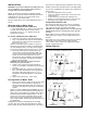
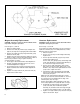
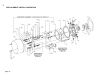
Numbers in parentheses refer to parts illustrated in Figs. 2, 4
and 10.
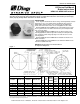
Mounting Hub on Motor Shaft
For models 6-60000-543 and 6-60000-5115:
1. Place rotating disc hub (1), with key, onto motor shaft
with part number facing away from motor to dimen-
sion shown in Fig. 2 (
21
/32 ±
1
/32). Measure from brake
mounting face as shown.
For models 6-60000-530 and 6-60000-5116:
1. Remove V-ring (30) from V-ring hub assembly (28).
2. Place V-ring hub assembly (28) onto motor shaft with
part number facing away from motor to dimension
shown in Fig. 2 (
21
/32 ±
1
/32).
NOTE: If motor shaft keyway extends into V-ring area,
install a key long enough to engage V-ring hub assembly
(28) and rotating disc hub (1). See Step 3 before tighten
ing setscrews. Tighten both setscrews to 35 lb. in. torque.
3. Place RTV sealant as shown (small amount to fill
crevices between V-ring hub assembly (.040” x 45°
chamfer), motor shaft, hub keyway and motor shaft
keyway. Use Dow Corning #739 RTV only; other
types may form acetic acid during curing if subjected
to water or high humidity. This will cause premature
failure of zinc plated parts.
CAUTION: If this proecedure is bypassed, liquid
media may seep into the brakes.
4. Replace V-ring (30) onto V-ring hub assembly as
shown in Fig. 2. Apply a small amount of grease to lip
of V-ring.
5. Place rotating disc hub (1) with key if not already in
place, onto motor shaft with part number facing away
from motor to dimension shown in Fig. 2 (
21
/
32 ±
1
/
32).
Rotating disc hub will butt against the V-ring hub as
shown.
6. Tighten both setscrews to 6 - 8 lb.ft. torque.
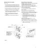
Placing Brake on Motor Shaft
1. Remove acorn nuts (23), washers (22), and cover (20).
Place brake on motor mounting face aligning hub
splines into brake disc splines. Make sure gasket (31)
is in place. Drain plug (25) to face down on horizontal
models.
NOTE: for models 4-60000-530 and 6-60000-5116 only: If
gasket (31) does not make contact around mounting face
totally (360°), exclude gasket (31) and place RTV sealant
around mounting bolt holes to approximately 1” dia. as
shown in Fig. 2. Use Dow Corning #739 RTV only; other
types may form acetic acid during curing if subjected to
water or high humidity. This will cause premature failure of
zinc plated parts.
If tapped holes in motor for mounting bolts are not totally
enclosed, place RTV sealant around threads before bolting
brake to motor. Use Dow Corning #739 RTV ony; other types
may form acetic acid during curing if subjeted to water or high
humidity. This will cause premature failure of zinc plated parts.
You may have to add drain in fan guard or other equipment as
shown in Fig. 2.
2. Tighten mounting bolts to 25 lb. ft. torque
3. Connect coil leads as outlined under “Connection of Coil
Leads” and Fig. 3.
4. Let RTV #739 cure 24 hours before replacing cover.
5. Replace cover (20) and fasten with three acorn nuts (23)
and washers (22). Tighten nuts to 5 lb. ft. torque.
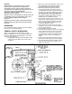
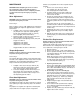
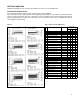
Connection of Coil Leads
After securing the brake to the motor, connect coil leads for
proper voltage per wiring diagram (Fig. 3 shows dual voltage
coil). Incorrect connection can result in brake failure.
CAUTION: The voltage supplied to the coil must match the
voltage that the coils are connected for, or the coils will
burn out.
Single voltage coil: Connect brake coil leads to any two line
leads (single or three phase) of same voltage and frequency
as brake.
Dual voltage coil: Connect leads 2 and 4 to any two motor line
leads (single or three phase) of same voltage as brake.
Connect leads 1 and 3 as shown for voltage desired. Brake
must be energized with motor.
Figure 3
Wiring Diagrams