
Manual
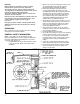
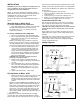
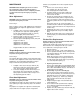
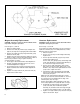
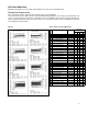
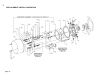

Figure 5
Magnet Assembly Replacement
CAUTION: Load to be removed or blocked. Brake will be
inoperative during this procedure.
Refer to Figs. 4, 6, and 10.
1. Disconnect power supply.
2. Remove acorn nuts (23), washers (22), and pull cover
(20) off. (You may have to tap lightly with a rubber mallet.
3. Remove two capscrews (15D), magnet assembly (15A),
and shock mount (15B).
4. Replace with new manget assembly, making sure shock
mount is in place. Feed coil wires through hole in back of
bracket (15C) as shown in Fig. 6. Tighten mounting
screws to 55-60 lb. in. torque.
5. Set air gap “A” as described under “Wear Adjustment”.
6. Energize coil. Magnet should be quiet; if not, refer to
“Pivot Stud Adjustment” on page 5.
7. Check manual release. If it does not operate properly,
adjust as outlined under “Manual Release Adjustment”
on page 7.
8. Replace cover (20), washers (22), and acorn nuts (23).
Tighten nuts to 5 lb.ft. torque.
Armature Replacement
CAUTION: Load to be removed or blocked. Brake will be
inoperative during this procedure.
Refer to Figs. 4, 5, and 10.
If you replace the magnet assembly, it may be necessary to
replace the armature (15J). If it is badly deformed, it will be
difficult to make the magnet quiet.
1. Disconnect power.
2. Remove cover per step 2 under “Magnet Assembly
Replacement”.
3. Remove operator assembly (15) per step 3 under
“Friction Disc Replacement”.
Remove nuts (15T), springs (15S), and carriage bolts
(15R). This will allow the armature plate assembly to
be removed from magnet bracket (15C).
4. Remove screw (15Q), lockwasher (15P), locking
plate (15N), two screws (15M), spacers (15L), and
armature (15J). Inspect these parts and shock mount
(15K). If worn, replace them also.
5. Put armature in place (ground side up) and install
spacers (15L) and screws (15M). Make sure shock
mount (15K) is in place.
NOTE: Screws (15M) should be tightened to remove
slack only. Then back off, counterclockwise on screw so
the next flat on screw is parallel with the edge of the
armature plate (15F). See Fig. 5.
Replace locking plate (15N0, lockwashers (15P), and
screw (15Q). Tighten screw (15Q) with 30 lb. in. torque.
6. Reassemble to magnet bracket (15C) using items
(15R), (15S) and (15T). Reassemble operator
assembly (15) to brake bracket. Set magnet air gap
“A” and set torque springs (15S) to 1” for all models.
7. Replace cover (20), washers (22), and acorn nuts (23).
Tighten nuts to 5 lb.ft. torque.
6
Figure 6