
Instruction Manual

60 Series Hazardous
Brake Instructions
DESCRIPTION
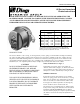
The 60 Series Brake is a direct acting, electro magnetically released, spring set unit that utilizes rotating and stationary
disc contact to supply positive braking action and quick release and setting capabilities at all times. Brakes which are
not provided with a floor mounting bracket are intended to be mounted as an integral part of electric motors listed for
corresponding hazardous locations where the acceptability of the combinations has been determined by Underwriter’s
Laboratories, Inc. The explosion-proof assembly is completed by assembly of the brakes to the motors.
READ THIS BULLETIN CAREFULLY BEFORE INSTALLING OR OPERATING THE
60 SERIES BRAKE. FAILURE TO COMPLY WITH THESE INSTRUCTIONS CANCELS
ALL WARRANTIES SINCE THE SAFETY OF THE UNIT MAY BE ENDANGERED BY
IMPROPER INSTALLATION OR OPERATING PROCEDURES.
Bulletin No. BK4614 (1/00)
4740 WEST ELECTRIC AVENUE MILWAUKEE, WI 53219 PHONE 414/672-7830 FAX 414/672-5354 www. dingsco.com
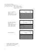
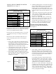
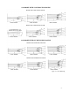
MOTOR MOUNTED* FOOT MOUNTED
ENCLOSURE ENCLOSURE
SUFFIX SUFFIX
MODEL
CAST MODEL CAST
NO. IRON ALUMINUM NO. IRON ALUMINUM
8-61001 -66B -67B F8-61001 -66B -67B
8-61003 -66B -67B F8-61003 -66B -67B
8-62006 -66B -67B F8-62006 -66B -67B
8-63010 -66B -67B F8-63010 -66B -67B
8-63015 -66B -67B F8-63015 -66B -67B
*If a hazardous location brake is purchased by other than an
authorized electric motor manufacturer, a Foot Mounted brake
must be purchased to obtain the UL label.
CAUTION
DO NOT OPERATE MANUAL RELEASE
OR ENERGIZE BRAKE COIL BEFORE
INSTALLATION IN ORDER TO PRESERVE
PRE-ALIGNMENT OF ROTATING DISCS
FOR EASE OF INSTALLATION.
USE ONLY HUB FURNISHED BY DINGS
SPECIFICALLY FOR USE IN HAZARDOUS
LOCATION BRAKES. DO NOT OPERATE
BRAKES IN EXPLOSIVE ATMOSPHERE
WITH COVER OR COVER BOLTS
REMOVED.
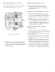
MANUAL RELEASE (See Figure 7)
To manually release brake, rotate release knob (41)
clockwise until it strikes stop-pin (39). Brake will remain
released until release knob is rotated counterclockwise, or
until power is restored, automatically resetting the brake.
THERMAL RELEASE
If the brake overheats, the thermal release mechanism
will release spring pressure on the friction discs, releasing
brake. To reset thermal release, allow brake to cool, then
rotate release knob (41) counterclockwise until it strikes
the stop-pin. Check brake operation as overheating may
indicate a broken lead wire or burned out coil.
The thermal release mechanism has been calibrated at the
factory and the setting of the bimetal element and control
rod MUST NOT BE DISTURBED. If the mechanism
does not function properly, the complete operator assembly
(44) must be returned to the factory for adjustment and
calibration.
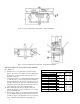
Figure 1