
Instruction Manual
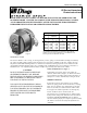
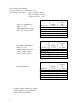
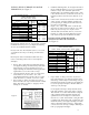
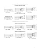

STANDARD MOTOR “C” FACE MOUNTING
NEMA FRAME SIZES
56C, 66C, 143TC, 145TC
DIMENSIONS
MODEL NO. WT. TORQUE AH
CAST IRON ALUMINUM LB. LB. FT. MAX. MIN.
8-61001-66B 40.5 1.5 2 3/8 1 3/4
8-61001-67B 23 1.5 2 3/8 1 3/4
8-61003-66B 40.5 3 2 3/8 1 3/4
8-61003-67B 23 3 2 3/8 1 3/4
8-62006-66B 43 6 2 3/4 2
8-62006-67B 24 6 2 3/4 2
8-63010-66B 45.5 10 3 1/8 2 1/4
8-63010-67B 25.5 10 3 1/8 2 1/4
8-63015-66B 45.5 15 3 1/8 2 1/4
8-63015-67B 25.5 15 3 1/8 2 1/4
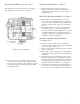
INSTALLATION OF BRAKE ON MOTOR
ENDSHIELD (See Figure 7)
Do not operate manual release or energize brake coil before
installation in order to preserve pre-alignment of rotating
disc for easy installation of brake to motor.
Because of the close fit on all joints (bracket, cover, hub),
care should be taken to prevent damage to all machined
surfaces.
Do not operate brake in hazardous location with cover
removed. All testing must be done in a non-explosive
atmosphere.
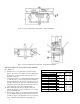
1. Remove hub (6) from brake and mount hub with key
(not supplied by Dings) on motor shaft per dimension
shown in Figure 5. Be sure that hub used is item
supplied by Dings for hazardous location applications.
Tighten both set screws to 8-10 lb. ft. torque.
2. Cast Iron Enclosure: Remove four cover bolts (42A)
and lockwashers (43) and remove cover (38A).
Cast Aluminum Enclosure: Remove four cover bolts
(42B), flat washer (9), locknut (8) and cover (38B).
3. Inspect motor “C” flange and remove any nicks or
burrs. This will assure a precision fit of brake to motor
flange. Slide brake over hub (6), engaging teeth of
rotating disc (2) and hub.
ADAPTER MOTOR “C” FACE MOUNTING
NEMA FRAME SIZES
182TC, 184TC, 213TC, 215TC, 254TC, 256TC
DIMENSIONS
MODEL NO. WT. TORQUE AH
CAST IRON ALUMINUM LB. LB. FT. MAX. MIN.
A8-61001-66B 47.5 1.5 2 3/16 2 3/16
A8-61001-67B 30 1.5 2 3/16 2 3/16
A8-61003-66B 47.5 3 2 3/16 2 3/16
A8-61003-67B 30 3 2 3/16 2 3/16
A8-62006-66B 50 6 3 3/16 2 7/16
A8-62006-67B 31 6 3 3/16 2 7/16
A8-63010-66B 52.5 10 3 9/16 2 11/16
A8-63010-67B 32.5 10 3 9/16 2 11/16
A8-63015-66B 52.5 15 3 9/16 2 11/16
A8-63015-67B 32.5 15 3 9/16 2 11/16
4. Install four mounting bolts (10) and tighten to 40 lb. ft.
torque. Install four locking set screws (11) and tighten
to 40 lb. ft. torque. This seals flame path around
mounting bolts. Check rotation of hub to make certain
it does not rub in bracket (5). Diametrical clearance of
hub outside diameter to bracket bore shall not exceed
.024”.
5. Connect brake coil leads to any two line leads of same
voltage as brake. All wiring should be positioned to
prevent pinching or chafing and all connections well
taped to prevent grounding.
6. Replace cover (38A or 38B). Make certain that two
pins of release shaft (35) fit over roll pin (32). A soft
mallet may be used to tap cover in place. Fasten
with four bolts (42A or 42B), washers (9 or 43) and
locknuts (8). A loose or missing bolt will render the
brake unsafe for operation in hazardous locations.
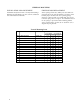
INSTALLATION OF BRAKE WITH
ADAPTER ON MOTOR ENDSHIELD
(See Figure 3)
7. Inspect motor “C” flange and remove any nicks or
burrs. This will insure a precision fit of adapter to the
motor flange. Mount adapter to motor flange using the
four bolts and lockwashers supplied. A soft mallet may
be used to tap adapter into place. All bolts should be
drawn up evenly and tight.
Check alignment of adapter. Clamp dial indicator to
brake hub (position A) and measure pilot eccentricity.
This must not exceed .002” total indicator reading for
a full revolution of hub. Reposition dial indicator
(position B) and check adapter face runout which
must not exceed .004” total indicator reading for a full
revolution of the hub. Remove hub (6) from brake and
mount hub with key (not supplied by Dings) on motor
shaft per dimension shown in Figure 3. Tighten both
setscrews to 8-10 lb. ft. torque. Complete mounting of
brake per paragraphs 2 through 6.
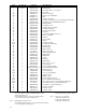
Figure 2.
5