
Instruction Manual
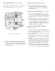

8. Install bracket (1) over motor shaft extension and half-
tighten cap screws (2). The distance from the mounting face
of the bracket (1) to end of motor shaft must not exceed
dimension “AH” max.
9. Clamp dial indicator “A” to motor shaft and position bracket
(1) with shims as necessary, by tapping with a soft mallet
until dial indicator does not read over .002” total change in
one full revolution of the shaft. Move dial indicator to “B”
and position bracket until dial indicator does not read over
.004” total change in one full revolution of shaft.
10. Draw all bolts up tight. Recheck alignment with dial
indicator. Readjust if necessary until tolerances are within
limits with all bolts tight.
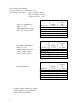
11. Remove hub (6, Figure 7) from brake and mount hub with
key (not supplied by Dings) on motor shaft per dimension
as shown in Figure 4. Tighten both setscrews to 8-10 lb. ft.
torque. Complete mounting of brake (paragraph 2-6).
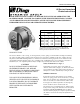
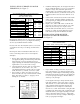
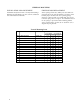
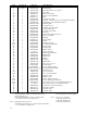
FOOT MOUNTING
DIMENSIONS
MODEL NO. WT. TORQUE AH
CAST IRON ALUMINUM LB. LB. FT. MAX. MIN.
8-61001-66B 40.5 1.5 2 3/8 1 3/4
8-61001-67B 23 1.5 2 3/8 1 3/4
8-61003-66B 40.5 3 2 3/8 1 3/4
8-61003-67B 23 3 2 3/8 1 3/4
8-62006-66B 43 6 2 3/4 2
8-62006-67B 24 6 2 3/4 2
8-63010-66B 45.5 10 3 1/8 2 1/4
8-63010-67B 25.5 10 3 1/8 2 1/4
8-63015-66B 45.5 15 3 1/8 2 1/4
8-63015-67B 25.5 15 3 1/8 2 1/4
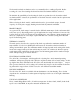
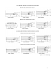
INSTALLATION OF FOOT MOUNTING BRAKE
(See Figure 4)
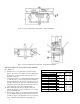
Figure 3. 60 Series Hazardous Location Brake - Adapter Installation
Figure 4. 60 Series Hazardous Location Brake - Foot Mount Installation
6