
Instruction Manual

WEAR ADJUSTMENT (See Figures 5 & 7)
When armature plate (12) touches bracket (5), closing gap
“B”, adjustment for friction disc wear is required.
12. To adjust, turn screws (16) clockwise until magnet gap
“A” reads .040” to .045” at narrowest gap, for 1 and 2
disc models and reads .050” to .055” at narrowest gap for
3 disc models. Any delay in adjusting gap will result in
eventual loss of torque.
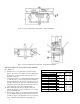
TORQUE ADJUSTMENT (See Figure 7)
13. Brake is factory set for rated torque. To increase
stopping time and lower torque, turn locknuts (45)
counterclockwise. Each full turn decreases torque by
approximately 10%.
FRICTION DISC REPLACEMENT (See Figure 7)
14. When total wear on rotating friction disc (2) reaches
1/16”, replace disc as follows. Loosen three mounting
screws (37), with release knob in release position, remove
operator assembly as a unit, spring (13), and stationary
disc (1).
15. Reassemble all parts in reverse order. Start all three of
the mounting screws (37), then turn two adjustment
screws (16) counterclockwise to allow the three operator
assembly mounting posts to seat against the bracket (5),
then tighten mounting screws. Readjust magnet gap, see
“Adjustment for Wear”, paragraph 12.
MAGNET ASSEMBLY REPLACEMENT
(See Figures 5 & 7)
16. To replace magnet assembly, unscrew two flat head
screws (31), remove magnet assembly (25) with shoulder
nut (23) and rubber washer (24).
17. Replace complete magnet assembly (25) and reassemble
parts in reverse order.
18. Magnet will be noisy, if magnet faces are not parallel in
closed position. Turn pivot nut (15) until minimum noise
is obtained.
19. If manual release does not work properly after resetting
pivot nut, set magnet gap “A” to read .040” to .045” at
narrowest gap, for 1 and 2 disc models and .050” to .055”
at narrowest gap for 3 disc models. Turn release shaft
clockwise until it strikes roll pin (39), releasing brake.
20. Adjust locknut (14) and jam nut (21B) until magnet gap
“A” is .030” at center of magnet face width. Manual
release must be in release position for this measurement.
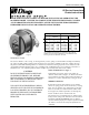
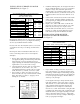
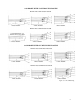
Figure 5. 60 Series H.L. Brake
7