
Instruction Manual
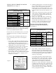
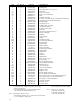

NO. OF ROTATING DISCS
CAST IRON ALUMINUM
ITEM DESCRIPTION PART NO. 1 2 3 1 2 3
1 SPRING (SILVER) G060350-001 2 2 2 2 2 2
2 SPRING (BLACK) G060350-002 - 2 2 - 2 2
3 SPRING (BRONZE) G060350-003 - - 2 - - 2
4 ROLLPIN - 1/8” X 5/8” W005003-071 2 - - 2 - -
5 ROLLPIN - 1/8” X 1” W005003-077 - 2 - - 2 -
6 ROLLPIN - 1/8” X 1-3/8” W005003-080 - - 2 - - 2
7 STATIONARY DISC H060203-003 - - - 1 1 1
8 STATIONARY DISC H060203-004 1 2 3 1 2 3
9 BRACKET - C.I. (1 DISC) L060032-101 1 - - - - -
10 BRACKET - C.I. (2 DISC) L060032-102 - 1 - - - -
11 BRACKET - C.I. (3 DISC) L060032-103 - - 1 - - -
12 BRACKET - C.A. (1 DISC) L060042-001 - - - 1 - -
13 BRACKET - C.A. (2 DISC) L060042-002 - - - - 1 -
14 BRACKET - C.A. (3 DISC) L060042-003 - - - - - 1
Vertical Mounting Parts
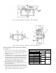
INSTALLATION AND ADJUSTMENT
Installation and adjustment of the vertically mounted Dings
Hazardous Location Brake is the same as on the standard 60
Series Hazardous Location Brake.
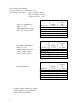
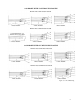
FRICTION DISC REPLACEMENT
When replacing friction discs, follow procedure outlined in
paragraphs 14 and 15, with this addition: Care must be taken
to insure proper insertion of the disc separating springs.
Springs are color-coded for easy identification, and reference
is made to spring color. See Figure 6. The installation order of
the disc springs is dependent on brake mounting position,
(above or below motor), so make sure to consult the correct
diagram for spring location.
VERTICAL MOUNTING
8