
Owner's manual

70 Series
Double “C” Face
Brake Instructions
IMPORTANT
Read carefully before attempting to assemble, install,
operate or maintain the product described. Protect yourself
and others by observing all safety information. Failure to
comply with instructions could result in personal injury
and/or property damage! Retain instructions for future
reference. When unpacking the brake, inspect it carefully
for damage that may have occurred during transit.
Bulletin No. BK4620 (11/13)
4740 WEST ELECTRIC AVENUEl MILWAUKEE, WI 53219l PHONE 414/672-7830 l FAX 414/672-5354 l www. dingsbrakes.com
WARNING
Brake performance and features must be carefully matched to the
requirements of the application.
Consideration must be given to torque requirements, especially where
an overhauling condition exists, as well as thermal capacity, ambient
temperature, atmospheric explosion hazards, type of enclosure and
any other unusual conditions.
Improper selection and installation of a brake and/or lack of mainte-
nance may cause brake failure which could result in damage to prop-
erty and/or injury to personnel.
If injury to personnel could be caused by brake failure, additional
means must be provided to insure safety of personnel.
DESCRIPTION
This brake is direct acting, electromagnetically released and spring set.
It uses rotating and stationary disc contact to supply positive braking
action. It retains quick release and setting capabilities at all times.
Simplicity of design has reduced maintenance to an absolute minimum.
As with any electromechanical equipment, however, periodic inspection
and adjustment will assure optimum performance. As the friction disc
wears, the magnet gap will increase. The magnet gap should be checked
periodically and adjusted when necessary. This brake is offered in 2
housing styles: Standard (NEMA 2) and Enclosed (NEMA 4).
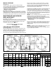
Figure 1. Wiring Diagram
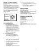
INSTALLATION
Refer to Figures 1 & 2
Insert key into motor shaft keyway. Key length to be as
shown below for models designated.
Used on all models except
71010, 71015, 72025, and
72035 with 1-1/8” dia. shaft.
For models 71010, 71015,
72025 and 72035 with
1-1/8” dia. shaft.
Slide brake onto motor shaft, aligning key in motor shaft
with keywayin brake shaft. Secure brake to motor “C” face
with four 1/2” socket head capscrews. Connect coil leads
per appropriate diagram.
Key must be full length
of keyway and flush with
end of shaft
Key to extend to
end of keyway
X
Model X ± 1/32
71010
71015
1-15/16
72025
72035
2-7/16