
User Manual

INSTALLATION
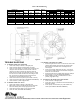
(See Figures 3 & 5, Tables 1 & 2)
1. Remove hub (1) from brake and position on motor shaft with key
according to dimension “N”. Stamped part number on hub should
face away from motor. Tighten hub set screws with 12 lb. ft. torque.
2. Remove cover screws (24) , cover (23) and gasket (28).
3. Place brake on motor, guiding discs on hub.
4. Bolt brake to motor “C” face with four 1/2 inch socket head cap
screws. See Figures 5 and 6 for screw length thru bracket.
5. Connect coil leads per appropriate wiring diagram in Figure 2 and
replace cover.
MANUAL RELEASE
(See Figure 3)
To operate release, rotate two rods(10) clockwise until stop screw
(14) hits pin. Release cap (29) must be removed by unscrewing,
before rods can be rotated.Brake will remain in released position until
rods are manually returned to original position, or until electrical power
is restored which automatically returns the release rods to the set
position.
TORQUE ADJUSTMENT
(See Figures 3 & 5)
Brake is factory set for rated torque per spring length “H”. To increase
stopping time and lower torque, turn four locknuts (9) counterclockwise,
increasing dimension “H”. All four springs must be set to the same
length. Do not decrease spring length “H” as this may cause coil to
burn out.
WEAR ADJUSTMENT
(See Figures 3 & 5, Table 2)
Magnet gap “D” increases as friction discs wear. When gap approaches
“D” max., adjust gap to “D” min. dimension by turning nuts (21 and 22).
Magnet gap can vary from nominal +
.005” between corners. After
setting gap, readjust torque spring length “H”.
CAUTION: MAGNET GAP MUST NOT EXCEED
“D” MAXIMUM.
FRICTION DISC REPLACEMENT
(See Figures 3 & 5, Table 2)
*When the rotating friction disc (4) wears down to a thickness of 7/32”,
replace disc.
1. Remove cover screws (24), cover (23) and gaskets (28 & 32).
2. Unhook loop of torsion springs (11) from pins at rear of magnet
plate (16). Remove release stop screws (14), washers (12) and
shims (13).
3. Remove adjusting lock nuts (22), magnet assembly (16), adjusting
nuts (21), torque nuts (9), washers (8), torque spring (7) and
pressure plate (6).
4. Remove friction disc (4) and stationary disc (5). Replace worn
friction discs.
5. Reassemble all parts in reverse order. Set spring length “H”
and magnet gap “D”. Assemble manual release. See following
paragraph.
MANUAL RELEASE ASSEMBLY
(See Figure 3)
When assembling a standard manual release mechanism (Figure 3),
add only enough shim washers (13) to obtain proper release action.
Too many shim washers will prevent automatic reset when electrical
power is applied. Too few washers will prevent the motor shaft from
turning freely. Replace stop screws (14). Wind each torsion spring (11)
approximately 1/4 turn and hook spring loop over pin.
MAGNET COIL REPLACEMENT
(See Figures 3 & 4)
Remove magnet assembly as outlined under FRICTION DISC
REPLACEMENT.
Coils (18) are held in place with epoxy cement. Force coil off magnet
mounting plate and remove excess epoxy from all surfaces.
Replacement coils should be held in place with new epoxy cement.
The epoxy cement should be heat resistant and shock resistant.
Place an insulating washer (19 or 19a) below the coils. Order insulating
washers when ordering coils. An insulating washer can be cut to suit
when replacing only one coil on a multiple coil assembly.
When installing coils, it is very important to follow EXACTLY the
sequence of black and light colored leads as shown in wiring diagram
(Figure 2). The brake will not operate properly unless coils are all in
the correct position.
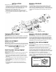
Figure 4. Fastening of Replacement Magnet Coils
Figure 3. Exploded View of Brake