
Manual
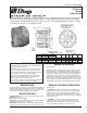

90 Series
Brake
Instructions
Read carefully before attempting to assemble, install, operate or maintain the product described. Protect yourself
and others by observing all safety information. Failure to comply with instructions could result in personal injury
and/or property damage! Retain instructions for future reference. When unpacking the brake, inspect it carefully
for damage that may have occurred during transit.
Bulletin No. BK4690 (8/02)
4740 WEST ELECTRIC AVENUE MILWAUKEE, WI 53219 PHONE 414/672-7830 FAX 414/672-5354 www. dingsco.com
DESCRIPTION
The 90 Series Brake is a spring set, electro magnetically released unit.
Heavy duty friction discs are standard and consist of non-asbestos
friction material bonded to an aluminum carrier. An automatic reset
manual release is standard (deadman release optional).
SPECIFICATIONS
MOTOR FRAMES - 324TC, 326TC, 364TC, 365TC, 404TC, 405TC
HOUSINGS - Cast iron.
DUTY - Rated for continuous duty.
VOLTAGES - All standard NEMA voltages and frequencies available.
Other voltages and frequencies are optional.
MOUNTING - Direct to NEMA “C” motor flanges. Adaptors for larger
or smaller frames, foot mounting and vertical mounting are available.
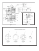
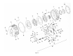
BRAKE OPERATION
Refer to Figure 3.
During brake setting, rotating discs (5), stationary discs (6), and the
pressure plate (7) are forced against the bracket (1) by the torque
springs (53) and (54), transmitted through the shock absorbers (46).
The friction developed between the discs is transmitted through the
rotating discs and hub (3) to the motor shaft as torque. When the
magnet coils are energized, the magnetic field generated attracts the
pressure plate; the rotating discs, hub and shaft are then free to turn.
As the friction discs wear, the magnet gap will increase. The magnet
gap should be checked periodically and adjusted when necessary.
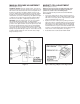
MANUAL RELEASE OPERATION
Refer to Figure 3.
1. AUTOMATIC
-
Turning the release knob (9) clockwise until it
stops, will release the brake. It will remain in the released position
until the knob is manually returned to its original position, or until
magnet coils are energized which automatically returns the knob to
its original position. NOTE: Due to the size of the discs, a slight drag
is common (5-7 lb. ft.).
2. DEADMAN
-
Turning the release knob (9) clockwise until it
stops, will release the brake. Knob will immediately return to its
original position when the turning force is removed. NOTE: Due to
the size of the discs, a slight drag is common (5-7 lb. ft.).
Figure 1.
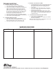
WARNING
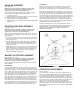
Brake performance and features must be carefully matched to
the requirements of the application.
Consideration must be given to torque requirements, especially
where an overhauling condition exists, as well as thermal
capacity, ambient temperature, atmospheric explosion hazards,
type of enclosure and any other unusual conditions.
Improper selection and installation of a brake and/or lack of
maintenance may cause brake failure which could result in
damage to property and/or injury to personnel.
If injury to personnel could be caused by brake failure, additional
means must be provided to insure safety of personnel.
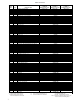
MODEL NO. INERTIA
STD. ENCL. SEVERE TORQUE WK
2
WEIGHT
HSG. HSG. DUTY HSG. LB. FT. C R AC LB. FT.
2
LBS.
2-92180-30 4-92180-31 6-92180-32 180 10 3/8 6 3/4 2.53 1.00 195
2-93270-30 4-93270-31 6-93270-32 270 10 3/8 7 1/2 2.53 1.38 205
2-94360-30 4-94360-31 6-94360-32 360 11 1/2 7 1/8 3.65 1.84 240
2-95450-30 4-95450-31 6-95450-32 450 11 1/2 7 7/8 3.65 2.30 250