
Manual


MANUAL RELEASE ADJUSTMENT
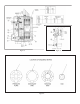
(Refer to Figures 3, 7 & 9.)
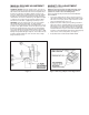
AUTOMATIC RETURN: Check the manual release. Turn cam (27)
clockwise until it stops. The brake should now be released. The cam
and manual release shaft should return to its normal position when
the brake is energized. If not, adjust as follows: Loosen the cap-
screw (36). With the brake energized and the cam turned clockwise
the stop, turn eccentric bushing (37) until the bearing (38) makes
contact with the cam surface. Hold bushing in this position and tight-
en capscrew. Check manual release for proper operation. NOTE:
Due to the size of the discs, a slight drag is common (5-7 lb. ft.).
DEADMAN: Check the manual release. Turn cam (27) clockwise
until it stops and hold it in this position. The brake should be
released. The cam should return to its normal position when you let
go of cam. If not, adjust as follows: Loosen the capscrew (36). WIth
the brake de-energized and the release cam in its normal position,
turn eccentric bushing (37) until the distance between the bearing
(38) and face on cam (27) measures .21 inches. See Figure 7. Hold
bushing in this position and tighten capscrew. Check manual release
for proper operation. NOTE: Due to the size of the discs, a slight
drag is common (5-7 lb. ft.).
MAGNET COIL ADJUSTMENT
(Refer to Figures 2, 3, 8 & 9.)
NOTE: Do not remove operator assembly from brake, unless
motor load is blocked. Removal of operator or blocking of
operator arm, results in loss of all braking torque.
Remove operator assembly as outlined under FRICTION DISC
REPLACEMENT.
1. Coils (18) are held in place by epoxy cement or by bent over
end magnet laminations. Force coil off magnet if held by epoxy
and remove excess epoxy from the magnet surfaces, or bend
up the end laminations and remove coil.
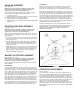
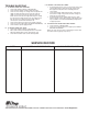
2. Replacement coils are held in place by bending of end lamin-
ations. (See Figure 8.) Insulating washers (19) are used above
and below the coil on replacements. Order insulating washers
when ordering a coil. When installing coils, it is very important
to follow EXACTLY the sequence of the black and white leads
as show n in the wiring diagram. Brake will not operate properly
unless coils are in the correct position. (See Figure 2.)
3. Reassemble brake as outlined under INSTALLATION.
Figure 8. Fastening of Replacement Magnet Coils
Figure 7.