
User guide

Page 1 of 3
12V 300W CLASS 2 MAGNETIC DIMMABLE DRIVER INSTALLATION GUIDE
Before you begin, read all warnings and installaon instrucons thoroughly.
Safety & Warnings
• This driver must be installed in accordance with Arcle 450 of the
Naonal Electric Code, and local regulaons.
• This product is to be installed and serviced by a qualied electrician.
• This driver must be grounded to the green grounding wire.
• Install in a well-venlated area free from explosive gases and vapors.
• This product is rated for indoor installaon and is not protected
against moisture.
• Only install compable LED dimmable xtures. Contact technical
support or visit the online product page for compable products.
• Do not modify or disassemble this product beyond instrucons or the
warranty will be void.
• Ensure applicable wire is installed between driver, xture, and any
controls in between. When choosing wire, factor in voltage drop,
amperage rang, and type (in-wall rated, wet locaon rated, etc.).
Inadequate wire installaon could overheat wires, and cause re.
• This specic model driver may be installed with an ON/OFF switch or
a compable Magnec Low Voltage (MLV) dimmer switch. Visit the
online product page for a list of compable dimmer switches.
• Ulize the wiring diagrams in this installaon guide for basic
installaons.
• When installing with a dimmer switch, see dimmer switch specs for
minimum load requirements.
Installaon
1. Turn power OFF at main circuit breaker.
2. Determine locaons to install the driver, xture and control. See ‘System Diagram.’
3. Remove both driver faceplates and pop out wiring knockouts as needed. Install 1/2” Romex connectors/wire strains. Feed wire through
Romex connectors prior to making wiring connecons.
4. Aach the appropriate load to the dimmable driver.
5. Aach the 120VAC MLV dimmer/switch to dimmable driver. Follow the install instrucons provided with the control.
6. Replace driver faceplates and turn power ON at main circuit breaker.
Install in accordance with the NEC and local regulaons. It is recommended to perform a dry test prior to permanent installaon to ensure all system
components are funconing properly.
Ensure applicable wire is installed between driver, xture, and dimmer. When choosing wire, factor in voltage drop, amp rang, and type to prevent
re or electric shock.
Reset Breaker
Both primary and (6x) secondary circuits are protected with a reset
breaker in the event of an overload, surge, or short circuit. A tripped
circuit is indicated by a popped out, white edge. To reset, turn o
main power and push in buon.
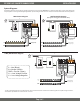
Boost Tap
Use the Orange Boost Tap as an oponal voltage boost (roughly 1V)
in place of the Black (Line) wire if the xture is receiving noceable
light degradaon. Cap the exisng hot wire not in use.
L
B
From Driver
From Dimmer
Switch
L
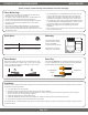
MounngQuick Specs
– 1 + – 2 + – 3 +
– 4 + – 5 + – 6 +
1 2 3
4 5 6
120VAC
12VDC
For proper heat dissipaon,
mount vercally to a sturdy
surface, with 120VAC
compartment facing upwards.
Mounng holes are located
inside driver compartments.
Input Voltage 120VAC
Output Voltage 11.2DC (Full Load)
Max Load
6 x 50W/4.2A
(50W taps do not require load derang)
If breaker trips (indicated by a white edge), turn
off main power and push in to reset breaker.
1
Breaker is now reset.
2