
Manual

1.877.817.6028
www.DiodeLED.com
info@DiodeLED.com www.DiodeLED.com
INSTALLATION GUIDE
1 OF 5
DMX WIFI WALL MOUNT ZONE LED CONTROLLER
®
DO NOT CONNECT DIRECTLY TO HIGH VOLTAGE POWER!
Read all warnings and installaon instrucons thoroughly.
WARNING
Safety & Warnings
• Install in accordance with the Naonal Electric Code, and local
regulaons.
• This product is intended to be installed and serviced by a qualied,
licensed electrician.
• DO NOT connect directly to high voltage power. Install with a compable
Class 2 constant voltage LED driver (power supply).
• Only install compable LED drivers and xtures. Contact technical
support or visit the product page for compable products.
• This product is rated for indoor installaon and is not protected against
moisture.
• Proper heat dissipaon will prolong the working lifespan of this product.
Install in a well-venlated area free from explosive gases and vapors.
• Ensure applicable wire is installed between driver, xture, and any
controls in between. When choosing wire, factor in voltage drop,
amperage rang, and type (in-wall rated, wet locaon rated, etc.).
Inadequate wire installaon could overhead wires, and cause a re.
• Do not modify or disassemble this product beyond instrucons or the
warranty will be void.
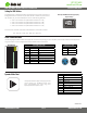
Quick Specs
Input Voltage 12-24VDC constant voltage
Transming Distance 40 . in open area
Output Signal
DMX512
Ambient Temperature † -4° ~ 104°F (-20° ~ 40°C)
Included Models
DI-1917
† Do not install product in an environment outside the listed ambient
temperature.
Prior to installaon, verify all components are a compable system. Congure and pre-test your LED system prior to permanent installaon to ensure all
components are operang correctly. Install in accordance with the NEC and local regulaons.
Installation
WARNING
Shock Hazard. May result in serious injury or death.
Turn OFF High Voltage AC Power at the main breaker.
1
ON
OFFOFFOFF
ONON
OFFOFF
ONON
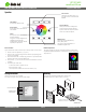
Determine Locaons to Install 3 Main Components.
2
1) Driver 2) DMX WiFi
Controller
3) Fixture(s)
Determine an accessible locaon to install a compable driver between the
main breaker and DMX WiFi Controller. Also, determine locaons to install
addional system components such as DMX xtures, controllers, etc.
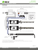
Connect the DMX WiFi Controller to driver and DMX xture.
Only use copper wiring. Reference ‘Wiring Connecons’, ‘System
Diagram’, and ‘Mounng’ located further in guide for visuals.
3
Install Addional Components, Verify Connecons, and Turn
Main Power ON at Breaker. Then address DMX decoders/
xtures. See ‘Seng the DMX Address.’
ON
OFFOFFOFF
ONON
OFFOFF
ONON
If system remains unresponsive or is working improperly, turn OFF
main power at breaker and verify all connecons. Review the ‘Wiring
Connecons’ and ‘Troubleshoong’ secons.
4
IG061814-1.2
DO NOT CONNECT
TO HIGH VOLTAGE
Dry Location Only
12V
DC
24V
DC