
Manual

1.877.817.6028
www.DiodeLED.com
info@DiodeLED.com www.DiodeLED.com
INSTALLATION GUIDE
3 OF 5
DMX WIFI WALL MOUNT ZONE LED CONTROLLER
®
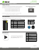
Pinout Connection Guide
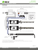
Dynamic Mode Chart
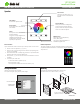
Setting the DMX Address
IG061814-1.2
Each DMX decoder or DMX xture needs to be addressed correctly so the controller can
disnguish between each decoder. To pair a DMX decoder or xture to a specic zone of
the controller (1-4), set each decoder/xture to one of the following addresses:
• Zone 1: Set to address ‘001’ (will be xed to address 001 – 004)
• Zone 2: Set to address ‘005’ (will be xed to address 005 – 008)
• Zone 3: Set to address ‘009’ (will be xed to address 009 – 012)
• Zone 4: Set to address ‘013’ (will be xed to address 013 – 016)
Each zone of the controller is xed with 4 DMX addresses to control the 4 channels:
CH1 – Red, CH2 – Green, CH3 – Blue, CH4 – White or X.
Example of DMX Addressing Display
Digital Display
The following diagrams/tables indicate the appropriate connecons for patching your own CAT5/RJ45, and XLR-3 splice cables. These diagrams are
for general reference and may slightly dier between dierent cable manufacturers.
1 2 3 4 5 6 7 8
RJ45 568B Pinout Table
Pin No. Wire Color Funcon
1 White/Orange Data +
2 Orange Data -
3 White/Green None
4 Blue None
5 White/Blue None
6 Green None
7 White/Brown May be used as 2nd ground
8 Brown Ground
XLR-3 Pinout Table
Pin No. Funcon
1 Ground
2 Data -
3 Data +
Mode Descripon
1 Full Color Fade #1
2 Reverse Rainbow Fade
3 Random Full Color Fade
4 7 Color Jump
5 RGB Fade In / Fade Out
6 RGB Fade In to O
7 RGB On to Fade Out
8 RGB Jump
9 Full Color Fade #2
10 Pastel Color Fade In / Fade Out
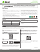
The Dynamic Mode tool plays factory-programmed
scenes. Choose up to 10 dierent scenes. Short
press switches/pauses the mode. Long press
adjusts speed of the dynamic mode.