
User Manual

1.877.817.6028
www.DiodeLED.com
info@DiodeLED.com www.DiodeLED.com
INSTALLATION GUIDE
1 OF 3
DMX WIRELESS TRANSMITTER / RECEIVER
®
DO NOT CONNECT DIRECTLY TO HIGH VOLTAGE POWER!
Read all warnings and installaon instrucons thoroughly.
WARNING
Safety & Warnings
• Install in accordance with the Naonal Electric Code, and local
regulaons.
• This product is intended to be installed and serviced by a qualied,
licensed electrician.
• DO NOT connect directly to high voltage power. Install with a compable
Class 2 constant voltage LED driver (power supply).
• Only install compable LED drivers and xtures. Contact technical
support or visit the product page for compable products.
• This product is rated for indoor installaon and is not protected against
moisture.
• Proper heat dissipaon will prolong the working lifespan of this product.
Install in a well-venlated area free from explosive gases and vapors.
• Ensure applicable wire is installed between driver, xture, and any
controls in between. When choosing wire, factor in voltage drop,
amperage rang, and type (in-wall rated, wet locaon rated, etc.).
Inadequate wire installaon could overhead wires, and cause a re.
• Do not modify or disassemble this product beyond instrucons or the
warranty will be void.
Quick Specs
Input Voltage 5VDC Constant Voltage
Transming Distance 1000 . eecve open area
Wireless ID’s
7 color-coded ID’s: Red, green,
yellow, blue, pink, cyan, white.
Ambient Temperature † -4° ~ 104°F (-20° ~ 40°C)
Included Models
DI-0820, DI-0821
† Do not install product in an environment outside the listed ambient
temperature.
Prior to installaon, verify all components are a compable system. Congure and pre-test your LED system prior to permanent installaon to ensure
all components are operang correctly. Install in accordance with the NEC and local regulaons. Both male or female transmiers may be installed as
a transmier and/or receiver.
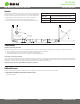
Installation
Power up the master DMX512 xture. If controlling independently
(no addional DMX controller), set the address to ‘001’. If controlling
with a separate DMX controller, see the controller instrucon
manual for addressing informaon.
1
Aach a single DMX transmier to the Master xture. Aach
the adapter to the transmier and plug the adapter into a
120VAC receptacle.
2
Using a thin screwdriver or stylus, press the recessed buon on
the transmier to cycle to the desired wireless network.
(Red, green, yellow, blue, purple, cyan, or white)
3
Power up the rst Slave xture. Address to ‘002’ if no separate
DMX controller is being installed. Aach a single DMX receiver
and aach the included plug-in adapter. Cycle to the same
wireless network the Master xture is addressed to.
4
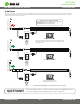
The transmier on the Master xture should now be blinking
red, while the receiver aached to the rst slave should be
blinking green. If the transmiers are not connecng, perform
a ‘so reset’ by cycling through all of the programmed modes of
the Master xture. A data signal may not transmit if the Master
xture is inially xed to a stac color. Performing a so reset or
cycling to a dynamic mode will iniate data transmission.
5
Connue adding addional Slave xtures. Ensure to address
each addional slave xture with an individual address (e.g.
‘003’, then ‘004’, etc.). Addressing Slave xtures to the same ID
will cause signal issues.
See ‘System Diagram’ for illustraons. See the product web page for
addional system designs including a remote DMX controller installaon.
6
DO NOT CONNECT
TO HIGH VOLTAGE
Dry Location Only