
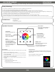
User guide

2 OF 4
INSTALLATION SHEET
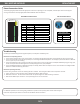
Seng the DMX Address
DMX 4-ZONE WIFI CONTROLLER
Each DMX decoder or DMX xture needs to be addressed correctly so the controller
can disnguish between each one. To pair a DMX decoder or xture to a specic
zone of the controller (1-4), set each decoder/xture to one of the following
addresses:
• Zone 1: Set to address ‘001’ (will be xed to address 001 – 004)
• Zone 2: Set to address ‘005’ (will be xed to address 005 – 008)
• Zone 3: Set to address ‘009’ (will be xed to address 009 – 012)
• Zone 4: Set to address ‘013’ (will be xed to address 013 – 016)
Each zone of the controller is xed with 4 DMX addresses to control the 4 channels:
CH1 – Red, CH2 – Green, CH3 – Blue, CH4 – White or X.
1 2 3 4 5 6 7 8 9 10
ONDIP
001
002
004
008
016
032
064
128
256
FUN
ON
OFF
Examples of DMX Addressing Displays
Digital Display
Dip-Switch Display
Install in accordance with the NEC and local regulaons.
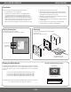
MounngWiring Connecons
DO NOT connect directly to 120VAC.
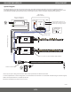
See ‘System Diagram’ for a general system design.
Pop o faceplate with
a athead screwdriver.
Install with the included DMX controller wall box.
Box dimensions:
2.83 x 1.89 x 2.83 in. (L x W x H)
Installaon
1. Turn power OFF at main circuit breaker.
2. Determine an accessible locaon for a compable driver to
be installed between the main breaker and DMX controller.
Determine a locaon to install addional accessories such as
DMX decoders, xtures, etc. Ensure applicable wire is installed
between all components. When choosing wire, factor in voltage
drop, amp rang, and type to prevent re or electric shock.
3. Remove the exisng wall plate and switch. Pull switch from wall.
4. Idenfy wires and disconnect from switch.
5. Remove exisng switch box from wall and install the included
DMX controller switch box. Addional tools may be required
to t DMX controller switch box in the wall.
6. Make wiring connecons. See ‘Wiring Connecons’ and ‘System
Diagram’ for addional informaon.
7. Replace wiring back into switch box. Mount and align controller.
See ‘Mounng.’
8. Turn power ON at main circuit breaker, and address DMX
decoders/xtures. See ‘Seng the DMX Address.’
GND
Data +
Data -
Vin (V+)
GND (V-)
To DMX Decoder
or DMX Fixture
From 12-24V Driver
Reset
Switch