
User guide
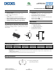

FMMT415-FMMT417
Datasheet Number: DS33084 Rev. 5 - 2
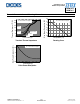
4 of 7
www.diodes.com
February 2014
© Diodes Incorporated
FMMT415
FMMT417
A
Product Line o
f
Diodes Incorporated
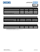
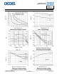
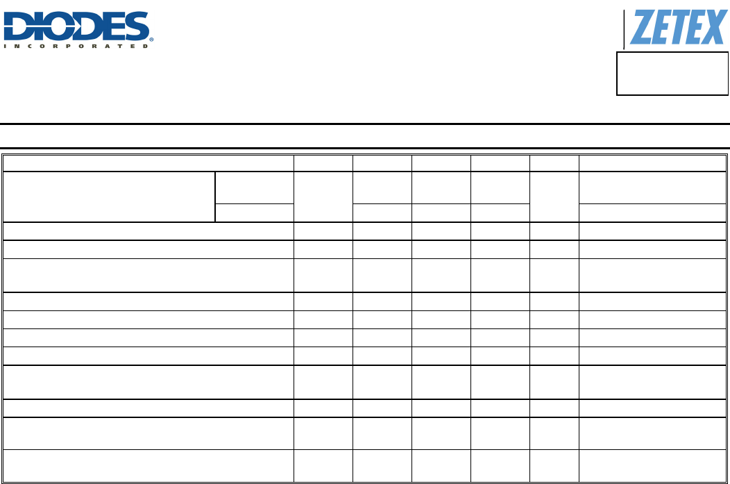
Electrical Characteristics (@T
A
= +25°C, unless otherwise specified.)
Characteristic Symbol Min Typ Max Unit Test Condition
Collector-Emitter Breakdown Voltage
FMMT415
BV
CES
260 — —
V
I
C
= 1mA
T
J = -55 to +150°C
FMMT417 320 — —
I
C
= 1mA
Collector-Emitter Breakdown Voltage (Note 8)
BV
CEO
100 — — V
I
C
= 100µA
Emitter-Base Breakdown Voltage
BV
EBO
6 — — V
I
E
= 100µA
Collector Cutoff Current
I
CBO
— —
100
10
nA
µA
V
CB
= 180V
V
CB
= 180V, TJ = +100°C
Emitter Cutoff Current
I
EBO
— — 100 nA
V
EB
= 4V
Static Forward Current Transfer Ratio (Note 8)
h
FE
25 — — —
I
C
= 10mA, V
CE
= 10V
Collector-Emitter Saturation Voltage (Note 8)
V
CE(sat)
— — 500 mV
I
C
= 10mA, I
B
= 1mA
Base-Emitter Saturation Voltage (Note 8)
V
BE(sat)
— — 900 mV
I
C
= 10mA, I
B
= 1mA
Pulsed Current in Second Breakdown
I
USB
15
25
—
—
—
—
A
A
V
C
= 200V, C
CE
= 620pF
V
C
= 250V, C
CE
= 620pF
Collector-emitter inductance
L
ce
— 2.5 — nH Standard SOT23 leads
Output Capacitance
C
obo
— — 8 pF
V
CB
= 20V, I
E
= 0
f = 100MHz
Transition Frequency
f
T
40 — — MHz
V
CE
= 20V, I
C
= 10mA,
f = 20MHz
Note: 8. Measured under pulsed conditions. Pulse width ≤ 300µs. Duty cycle ≤ 2%.