
User guide

MBR2060CTP
Document number: DS31794 Rev. 4 - 2
2 of 4
www.diodes.com
April 2011
© Diodes Incorporated
MBR2060CTP
NEW PRODUCT
Maximum Ratings (Per Leg) @T
A
= 25°C unless otherwise specified
Single phase, half wave, 60Hz, resistive or inductive load.
For capacitance load, derate current by 20%.
Characteristic Symbol Value Unit
Peak Repetitive Reverse Voltage
Working Peak Reverse Voltage
DC Blocking Voltage
V
RRM
V
RWM
V
RM
60 V
Average Rectified Output Current (Per Leg)
(Total)
I
O
10
20
A
Non-Repetitive Peak Forward Surge Current 8.3ms
Single Half Sine-Wave Superimposed on Rated Load
I
FSM
170 A
Isolation Voltage
From terminal to heatsink t = 1min.
V
AC
2000 V
Thermal Characteristics (Per Leg)
Characteristic Symbol Value Unit
Maximum Thermal Resistance, Junction to Case
R
θ
JC
3
°C/W
Operating and Storage Temperature Range
T
J
, T
STG
-65 to +175 ºC
Electrical Characteristics (Per Leg) @T
A
= 25°C unless otherwise specified
Characteristic Symbol Min Typ Max Unit Test Condition
Forward Voltage Drop
V
F
-
-
0.60
0.80
0.70
V
I
F
= 10A, T
J
= 25ºC
I
F
= 10A, T
J
= 125ºC
Leakage Current (Note 2)
I
R
-
6
4.2
100
20
μA
mA
V
R
= 60V, T
J
= 25ºC
V
R
= 60V, T
J
= 125ºC
Notes: 2. Short duration pulse test used to minimize self-heating effect.
3. Device mounted on Black Aluminum Heatsink, 37mm * 50mm * 15mm.
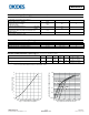
0
1
2
3
4
5
6
7
8
0246 8101214
Fig. 1 Forward Power Dissipation
I , AVERAGE FORWARD CURRENT (A)
F(AV)
P
,
P
O
WE
R
DISSI
P
A
T
I
O
N (W)
D
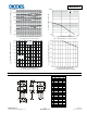
0.001
0.01
0.1
1
10
100
0 200 400 600 800 1,000
Fig. 2 Typical Forward Characteristics
V , INSTANTANEOUS FORWARD VOLTAGE (mV)
F
I , INSTANTANEOUS FORWARD CURRENT (A)
F